
audio graphic equalizer circuit

The gyrator circuit is a crucial element in analog signal processing, particularly in applications where inductance is required but physical inductors are impractical or undesirable due to size, cost, or performance issues. The active components, such as transistors or operational amplifiers, allow the circuit to simulate inductive behavior effectively.
In the described configuration, the transistor interacts with resistors R1 and R3, forming a feedback loop that establishes the necessary phase shift to emulate an inductor's behavior. The values of R1 and R3, along with the capacitance of C2, are critical in determining the circuit's performance characteristics, such as the center frequency and quality factor.
The center frequency (f) is a pivotal parameter, defined by the circuit's reactive components, and is calculated using the associated formula. This frequency indicates where the circuit will exhibit its peak response. The quality factor (Q) reflects the selectivity and bandwidth of the bandpass response, with a higher Q indicating a narrower bandwidth and sharper resonance.
The impedance presented by the gyrator circuit is a combination of resistive, capacitive, and inductive elements. The resistive component arises from the resistors, while the capacitive contribution comes from capacitor C1. The inductive term, which is the key feature of the gyrator, arises from the active device's operation, effectively allowing the circuit to behave as if it includes an inductor.
This configuration can be particularly advantageous in filter design, oscillators, and other applications where inductive elements are needed without the drawbacks of physical inductors. The gyrator's ability to simulate inductance through active components allows for greater flexibility and integration in modern electronic designs.A gyrator is a circuit using active devices and transistors to simulate an inductor. In this case the gyrator is the transistor acting with R1, R3 and C2. It could just as easily be a unity gain op-amp (which gives superior performance). The circuit includes three formulae: one which gives f, the centre frequency of the band. The second shows how the Q is related to the capacitor ratio. The third shows the impedance presented by the circuit. Note that this includes 3 terms, the first purely resistive, the second is the capacitive contribution from C1 and the third is an inductive term from the gyrator. 🔗 External reference
Related Circuits
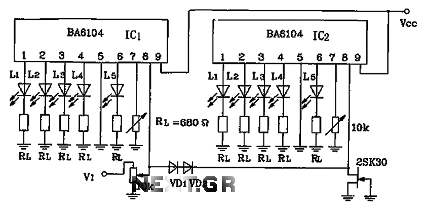
BA6104 is a five-digit LED level meter that functions as an LED display driver integrated circuit (IC). The configuration of the circuit is illustrated in the accompanying figure. The circuit utilizes a 10 by two-dot LED level display. The...
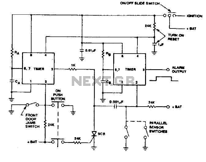
The 555 timer generates a reliable delay, enabling the driver to deactivate the alarm and eliminating the need for an external control switch that could be compromised. Additionally, the RCS prevents the activation of timer B unless it is...
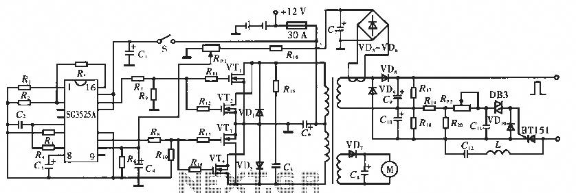
The circuit utilizes the SC3525A, a PWM silicon chip from US General Semiconductor. It features an error amplifier with an inverting input at pin 1. Pin 2 serves as the non-inverting input for the error amplifier. Pins 5 and...
This is a clap switch designed to avoid false triggering. To activate or deactivate any appliance, a user must clap twice. The circuit changes its output state only when two claps are detected within a specified time frame of...
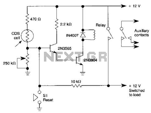
When light strikes the CDS cell, it activates the transistors, which in turn energizes the relay, causing it to latch. Pressing switch SI grounds the base of the 2N3565 transistor, thereby resetting the relay. Additionally, a 250 k potentiometer...
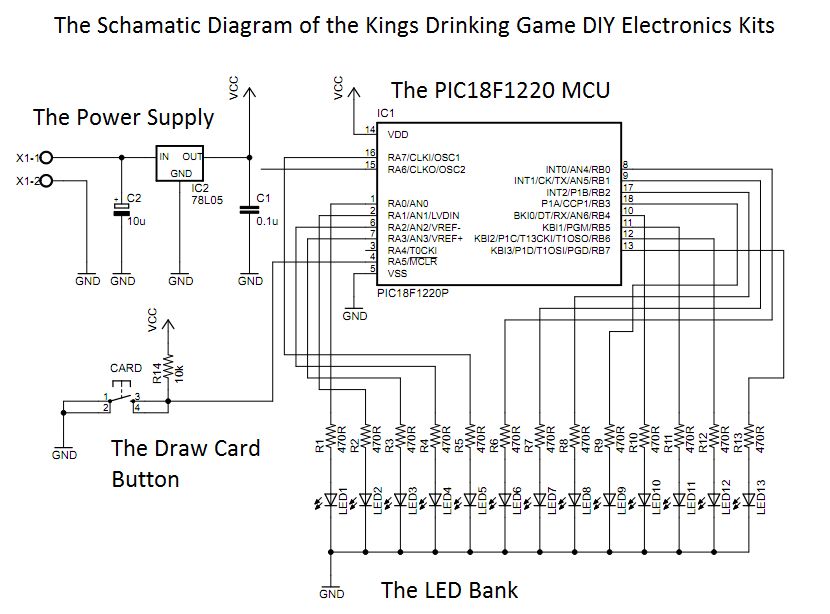
This circuit was designed approximately four months ago and has been developed into a kit for others to use. The circuit in question appears to be a well-thought-out design that has been packaged into a kit format, making it accessible...