
Audio oscillator

The Wien bridge oscillator is a precision waveform generator widely used in audio and signal processing applications. Its design is based on a bridge configuration that employs resistive and capacitive components to establish a frequency-dependent condition for oscillation. The key to its operation lies in maintaining a balance between the resistive and capacitive elements to achieve a specific phase shift that is essential for sustained oscillation.
The oscillator operates with a feedback mechanism that adjusts the gain dynamically. The use of a small lamp, which has a positive temperature coefficient, allows for self-regulation of the gain. As the output amplitude increases, the temperature of the lamp rises, leading to an increase in its resistance. This, in turn, reduces the gain, preventing distortion and ensuring that the loop gain remains at unity at the desired oscillation frequency.
The four frequency bands enable a wide range of applications, from low-frequency signal generation to high-frequency test signals. The ganged 20 k ohm potentiometers provide fine control over the frequency settings, allowing for smooth transitions across the frequency range. The current draw of 4.0 mA from the 9-V power supply indicates efficient operation, making it suitable for battery-powered applications.
The output characteristics of the oscillator are designed to deliver a stable sine wave with an amplitude of 4 to 5 V under a 10 k ohm load, making it compatible with various electronic circuits. The feedback resistor (Rf) is crucial in determining the clipping point, and setting it slightly below this threshold ensures that the output waveform remains undistorted.
For applications that require interfacing with DC circuits, the inclusion of a coupling capacitor is essential. This capacitor blocks any DC offset present in the output, allowing only the AC component of the signal to pass through, thus protecting downstream components from potential damage caused by DC levels.
Overall, the Wien bridge oscillator is a versatile and reliable circuit for generating low-distortion sine waves across a broad frequency spectrum, with features that enhance its usability in various electronic applications.A Wien bridge oscillator produces sine waves with very low distortion level. The Wien bridge oscillator produces zero phase shift at only one frequency (f = Vx t RC) which will be the oscillation frequency. Stable oscillation can occur only if the loop gain remains at unity at the oscillation frequency. The circuit achieves this control by using the positive temperature coefficient of a small lamp to regulate gain (Rf/RLAMp) as the oscillator attempts to vary its output.
The oscillator shown here has four frequency bands covering about 15 Hz to 150 kHz. The frequency is continuously variable within each frequency range with ganged 20 k ohm potentiometers. The oscillator draws only about 4.0 mA from the 9-V batteries. Its output is from 4 to 5 V with a 10 k ohm load and the Rf (feedback resistor) is set at about 5% below the point of clipping.
As shown, the center arm of the 5 k ohm output potentiometer is the output terminal. To couple the oscillator to a dc type circuit, a capacitor should be inserted in series with the output lead.
Related Circuits
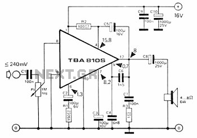
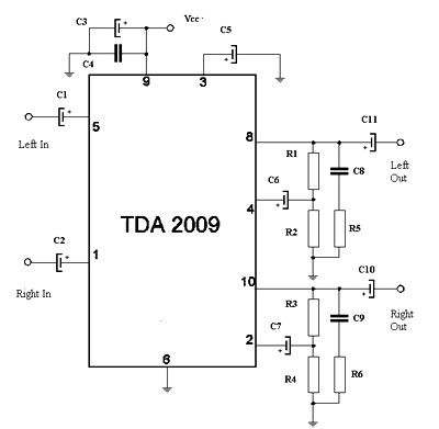
This circuit is a 7 Watt audio amplifier that is simple and easy to construct. It utilizes the TBA810 as the primary component, supported by a few passive components. The amplifier operates effectively, and the necessary kits and components...
This works with a small geleidingstestertje LM 3909. It allows a tester beeps when the resistance between the probes between 0 and 100 ? lies. Due to the volume of the beep, the resistance between the probes can be...
The modular Portable Mixer design presented on these web pages has gained popularity among many amateurs. However, some users have requested a simpler device specifically for mixing mono signals. This revised design aims to meet those requirements, incorporating three...
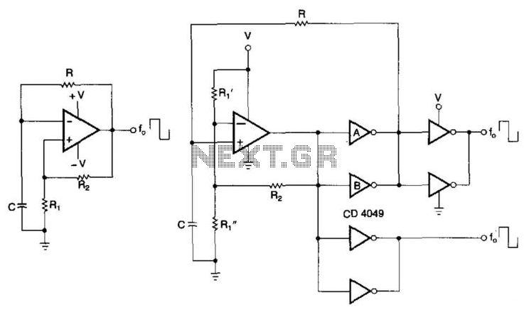
CMOS buffers added to an operational amplifier oscillator enhance performance, primarily due to the asymmetry and variability of the operational amplifier's output saturation voltages. The integration of CMOS buffers into an operational amplifier (op amp) oscillator circuit serves to significantly...
The circuit features a Class AB audio amplifier integrated circuit (IC) that necessitates only a minimal number of external components. This series is straightforward to construct. The 10W stereo amplifier circuit requires a stable power supply with a voltage...
A mixer circuit is being developed. There is uncertainty regarding its functionality, and a request for verification has been made. In this schematic, resistors R1 and R2 are utilized. The mixer circuit typically combines two or more input signals into...