
audio peak indicator

A peak level indicator circuit typically comprises a few essential components: an input stage, a signal conditioning stage, a peak detection stage, and an output stage. The input stage usually consists of an operational amplifier (op-amp) configured as a non-inverting amplifier to ensure that the incoming audio signal is adequately amplified without distortion.
The signal conditioning stage may include filters to eliminate unwanted noise and ensure that only the desired frequency range is processed. This stage may also involve a rectifier circuit, which converts the AC signal into a DC voltage proportional to the peak level of the audio signal.
The peak detection stage is critical, as it captures the maximum voltage level of the incoming signal. This is often achieved using a peak detector circuit, typically implemented with a diode and a capacitor. The diode allows current to flow in one direction, charging the capacitor to the peak voltage level, while the capacitor holds this charge, providing a stable DC voltage that represents the peak level of the input signal.
Finally, the output stage may include a visual indicator, such as an LED or an analog meter, to provide a clear visual representation of the peak level. The LED can be configured to illuminate when the signal exceeds the predetermined threshold, thus serving as a warning to the operator.
In summary, a peak level indicator is an essential tool in audio signal processing, ensuring that signals remain within acceptable limits to avoid distortion or clipping. Its design focuses on responsiveness to brief signals, making it a vital component in various audio applications.A peak level indicator when a signal exceeds a certain maximum value. It can be quite useful, for instance, with tape recorders, mixing consoles etc. One of the most important requirements of a peak level indicator is that it should respond to very short signals.. 🔗 External reference
Related Circuits
Blue VALUES replaced by values in RED. Blue COMPONENTS removed from circuit. Red components added to circuit. In this circuit modification, the original design underwent significant changes where blue values were substituted with corresponding red values to enhance performance or...
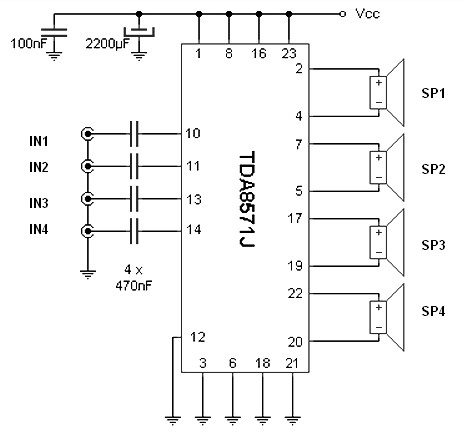
The integrated audio TDA8571J, designed for automotive applications, allows for the expansion of car radio sound or the connection of a portable MP3 player. Internally, the chip contains eight operational amplifiers set in a bridge configuration, enabling each speaker...
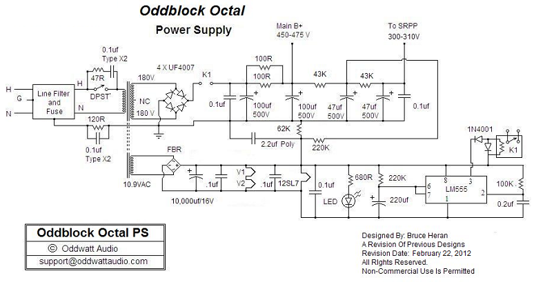
One of the advantages of hosting a hobby website is the opportunity to connect with individuals via email who share similar interests. Since posting Bruce's initial OddWatt project on the site, communication has occurred with numerous DIY hobbyists who...
An analog VU meter is commonly found in audio equipment to indicate signal levels in volume units. It features a peak LED and compares the response of the VU meter (represented by a black line) with the instantaneous input...
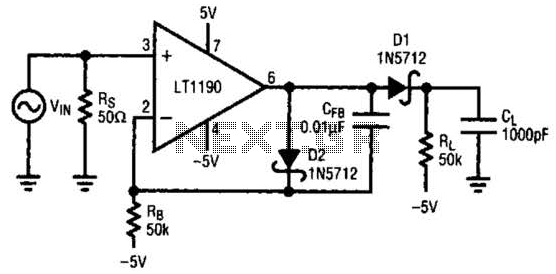
In this open-loop design, the detector diode is D1, and a level-shifting or compensating diode is D2. Load resistor RL is connected to -5 V, and an identical bias resistor RB is used to bias the compensating diode, also...

The input capacitor is used for low-frequency cut-off, with a standard value of 0.1 µF, resulting in a cut-off frequency of approximately 16 Hz. The input capacitor plays a critical role in electronic circuits, particularly in signal processing and audio...