
Audio Power Limiter

The circuit utilizes a Light Dependent Resistor (LDR) as a key component for gain control in an audio amplifier application. The LDR is characterized by its resistance decreasing with increasing light levels, making it suitable for automatic gain control (AGC) systems. The LDR is connected in a voltage divider configuration, where it pairs with a fixed resistor to form a reference voltage for the amplifier's input stage.
An LED is employed as the illumination source for the LDR. When the amplifier reaches a predetermined output level, the LED is activated, emitting light that strikes the LDR. As the LED brightness increases, the resistance of the LDR decreases significantly, leading to a reduction in the voltage at the amplifier's input. This feedback mechanism effectively stabilizes the output level by preventing the amplifier from exceeding the set threshold.
The circuit can be designed to include additional components such as operational amplifiers or transistors to enhance performance and provide further control over the gain characteristics. The choice of the fixed resistor in the voltage divider will determine the sensitivity of the gain control, allowing for adjustments based on the desired output level and response time.
The overall design ensures that the system maintains low distortion across a range of signal levels, providing a reliable and efficient method for automatic gain control in audio applications. The use of an LDR and LED combination not only simplifies the circuitry but also enhances the adaptability of the amplifier to varying input conditions, making it a robust solution for dynamic audio environments.The gain control element is a Light Dependent Resistor (LDR). These are blessed with a few very useful features for our purposes, one of which is low distortion even at quite high signal levels. Being light activated, all we need is a LED to provide illumination when the preset power level is reached.
Once this point is reached, a very small increase in amplifier output voltage (and power) will cause the LED to provide much more light, reducing the value of the LDR, and thus reducing the input voltage. The effect is to keep the level more or less const 🔗 External reference
Related Circuits

The circuit illustrated in Figure 4 is an AC timing circuit designed to operate for 4 hours. It utilizes the BH4024, a 7-stage serial binary counter/divider, in conjunction with a 555 timer circuit. The circuit is activated by a...
At low output power, up to 18 W, the device functions as a standard BTL amplifier. When a greater output voltage swing is necessary, the internal supply voltage is increased using external electrolytic capacitors. This momentarily elevated supply voltage...
Powering the system is required by many applications while charging the battery simultaneously. Interaction between the system and charger may result in a... Power management in electronic systems is critical, particularly in applications that necessitate simultaneous operation and battery charging....

This is a circuit for an audio frequency meter. This circuit utilizes a 555 IC configured as a monostable multivibrator (one-shot trigger). A monostable multivibrator can function as a frequency-to-voltage converter by producing a fixed pulse width, with the...
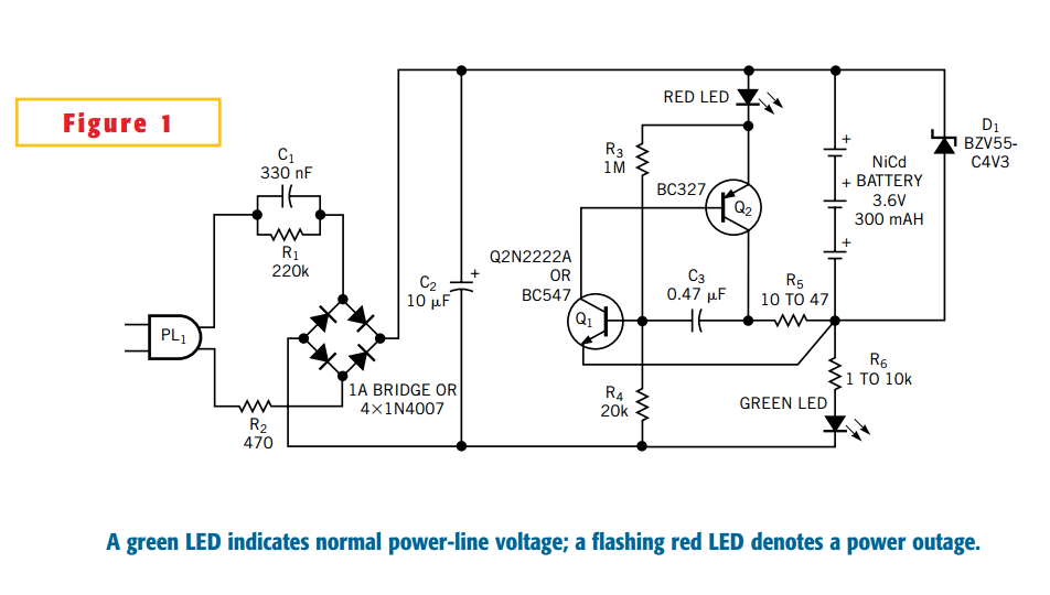
This Design Idea expands on a circuit in a previous one to configure a power-outage detector with a flashing alarm (Figure 1, Reference 1). The circuit plugs into a mains outlet and uses trickle-charged nickel-cadmium batteries. The green-LED monitors...
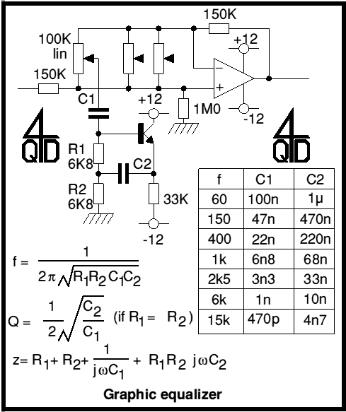
Audio graphic equalizers are very common as commercial products (for Hi-fi, car audio and stage use) but circuits for them are very rarely published. I didn't design this one but it's really very simple. The details shown are...