
Audio Tone Control

The described circuit is a Baxendall tone control circuit, which is renowned for its ability to adjust audio frequencies with precision while maintaining a flat response at the center frequency. This circuit employs a BC109C transistor as an input buffer, which is critical for maintaining high input impedance and ensuring that the signal is not significantly loaded by the subsequent stages. The input impedance of approximately 250kΩ allows for compatibility with various audio sources without degrading the signal quality.
The core of the Baxendall design features passive components, specifically resistors and capacitors, which dictate the frequency response of the circuit. The arrangement of these components allows for a maximum cut and boost of around 10dB at two specific frequencies: 10kHz and 50Hz. This characteristic makes the circuit particularly useful in applications where bass and treble adjustments are required, such as in audio mixing consoles or home audio systems.
The tone control circuit operates by varying the reactance of the capacitors in conjunction with the resistors, which in turn modifies the audio signal's frequency response. This interaction allows users to enhance or attenuate specific frequency ranges, thus shaping the overall sound character.
At the output stage, an additional transistor provides a gain of approximately three times the input signal, ensuring that the final output level is adequate for driving subsequent audio processing stages or amplifiers. The combination of passive tone control and the active gain stage allows for a versatile and effective audio processing solution, suitable for both professional and consumer audio applications.
In summary, the Baxendall tone control circuit effectively balances high input impedance, flexible frequency response adjustments, and sufficient output gain, making it an essential component in audio engineering.Based on the classic Baxendall tone control circuit, this provides a maximum cut and boost of around 10dB at 10K and 50Hz. The first BC109C transistor (left hand side) is acting as a buffer. It provides the circuit with a high input impedance, around 250k has a voltage gain of slightly less than unity.
As the Baxendall tone control circuit is a passive design, all audio frequencies are attenuated. The position of the controls and reactance of the capacitors alters the audio response. The last transistor provides a slight boost of about 3x. The output is 🔗 External reference
Related Circuits
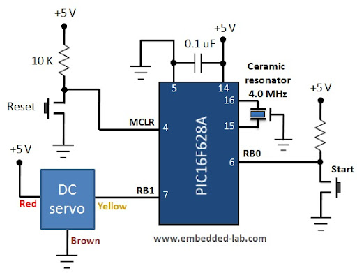
A servo motor is a specialized geared DC motor that includes an electronic circuit for controlling the direction and position of the motor shaft. Due to its capability for precise angular positioning, servo motors are widely utilized in robotics,...
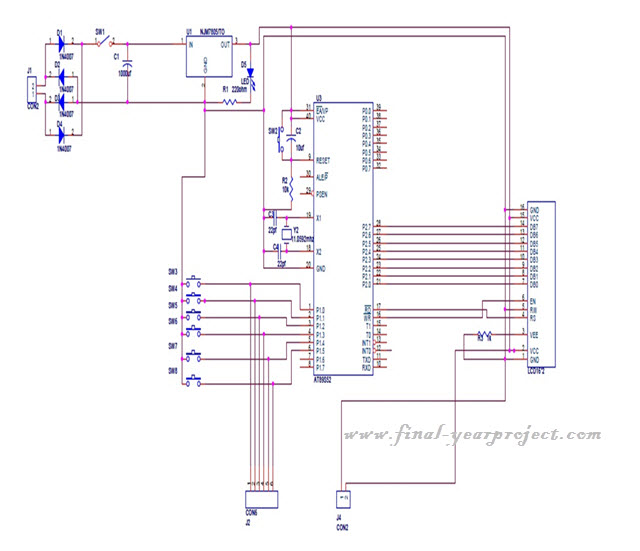
This project is a microcontroller-based college automation system aimed at addressing the challenges faced in educational institutions. It replaces the conventional notice board with an automated device that allows users to both hear and read the information being announced...
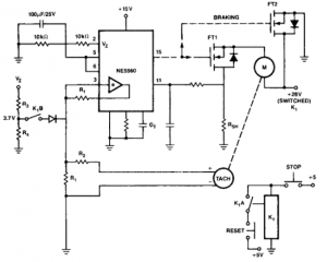
This circuit is useful for creating a constant speed motor control, ensuring that the motor speed remains constant despite variations in load and electrical voltage. The circuit for a constant speed motor control typically employs feedback mechanisms to maintain a...

This oscillator may contain several switched crystals to provide channelized operation. A buffer amplifier may be added if desired. The oscillator described is designed to utilize multiple switched crystals, enabling it to operate across various frequency channels. This feature is...
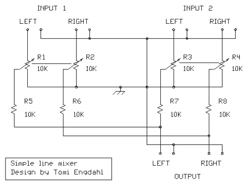
The mixer circuit described features three line inputs and three microphone inputs. The microphone inputs are designed for low impedance dynamic microphones with a range of 200 to 1000 ohms. Alternatively, an electret condenser microphone (ECM) can be used,...
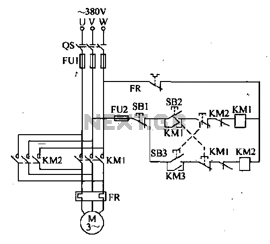
The forward and reverse dual interlock control circuit is based on the control circuit depicted in Figure 4-4, with an enhancement that incorporates a composite mechanical button interlock. The advantage of this circuit is that it allows the motor...