
Four crystal diode switching circuit diagram of the IF filter

The circuit described operates within the amateur radio frequency spectrum, utilizing a 9-12V DC power supply to energize the intermediate frequency (IF) amplifier. The choice between control points A and B allows for flexibility in circuit configuration, catering to different operational needs or preferences of the user. The specified frequency of 455 kHz is a standard for IF stages in communication receivers, which facilitates effective signal processing and demodulation.
The bandwidth of 500 Hz indicates that the amplifier is optimized for narrowband applications, which is particularly beneficial for CW signals, allowing for clearer reception of Morse code transmissions. The mention of a 300 Hz crystal frequency underlines the design's focus on CW operations, ensuring that the system can accurately filter and amplify signals characteristic of this mode.
In contrast, the parameters for SSB operation highlight the versatility of the circuit. The bandwidths of 1.8 kHz and 2.1 kHz suggest that the amplifier can handle a range of SSB signals, accommodating various transmission qualities. The ability to select between these bandwidths allows for adaptability depending on the specific requirements of the communication scenario.
Overall, this circuit design emphasizes the importance of tailored signal processing in amateur radio applications, ensuring that users can achieve optimal performance across different modes of communication. The thoughtful selection of frequency and bandwidth parameters plays a crucial role in enhancing the clarity and reliability of received signals.9-12V DC power applied to the control point A or point B, for amateur communication receiver IF amplifier, gives two different options. Power 455kHz, the bandwidth 500Hz, the f requency of the crystal is not used should be 300 Hz CW, not 2.7kHz SSB bandwidth is 1.8kHz, 2.1kHz SSB bandwidth when not 1.25kHz.
Related Circuits
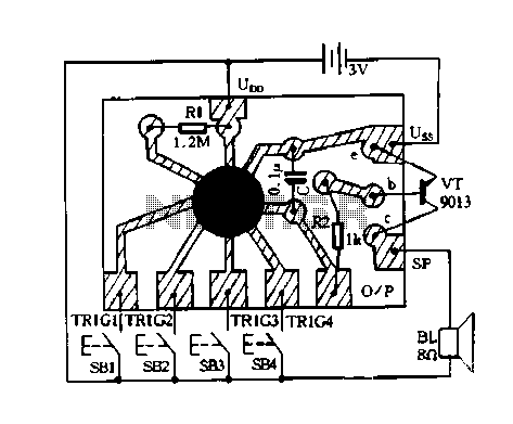
Constantly changing light and sound analog controller circuit 07 The circuit described is an analog controller designed to modulate light and sound in a dynamic manner. This circuit utilizes various electronic components to create an interactive experience where both light...
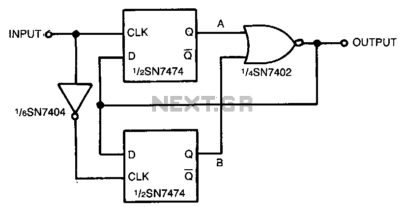
An input signal drives both SN74 D-type flip-flops, which are positive edge-triggered devices. A low-to-high input signal transition triggers the A flip-flop, while a high-to-low input signal transition triggers the B flip-flop via the SN7404 inverter. Either flip-flop in...

A basic LED driver circuit consists of a 5-volt power source, a 2 kΩ potentiometer, and an LED. The LED is forward biased, with the manufacturer specifying a maximum current rating of 20 mA at a diode voltage drop...
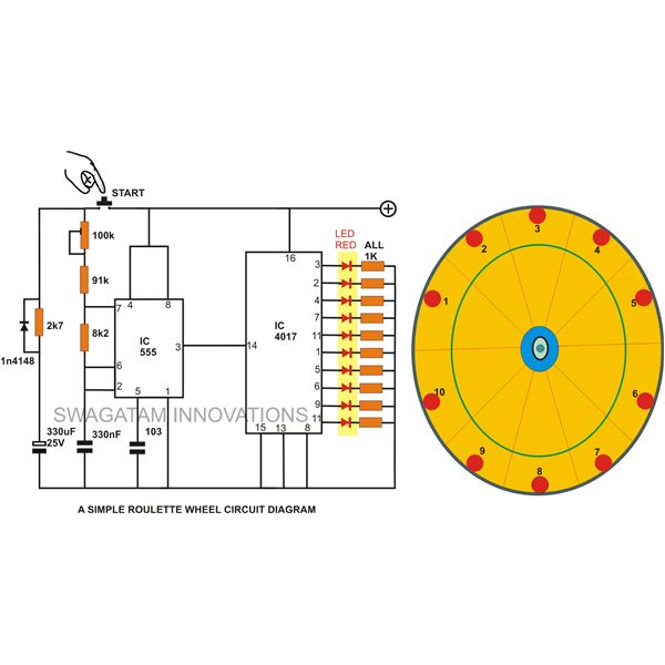
A simple circuit for a 10 LED roulette wheel is presented. Pressing the button initiates the LEDs in a rotational sequence that starts at full speed and gradually decelerates until it halts at a randomly selected LED. The randomness...
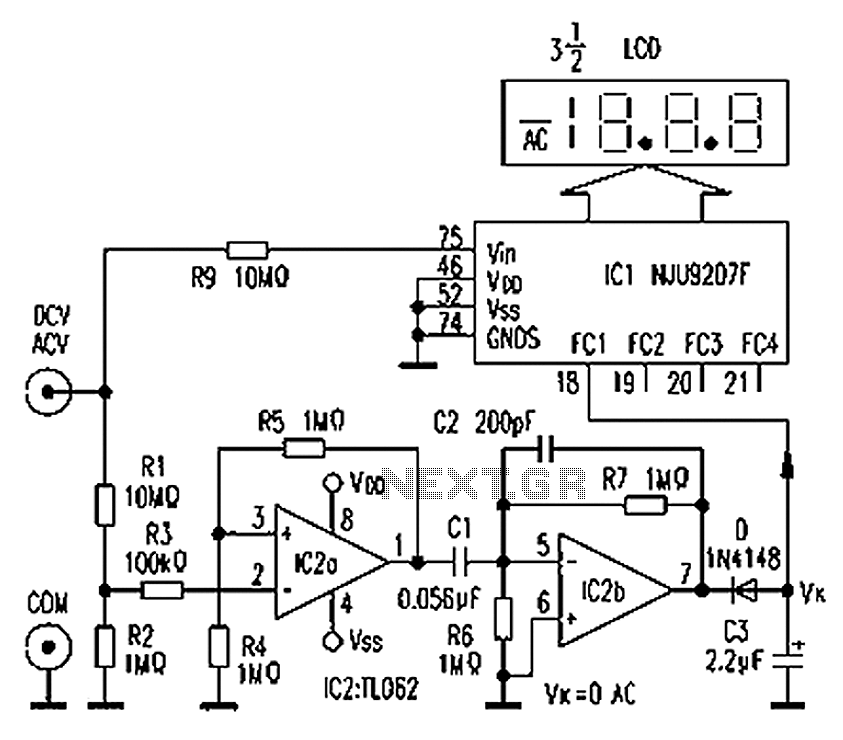
The circuit depicted in the figure illustrates an automatic AC/DC converter for a digital multimeter. Typically, standard digital multimeters require manual intervention to switch between AC and DC measurements. The new DT860D digital multimeter utilizes the NJU9207F automatic range...

The modification of the differential circuit is illustrated. In Figure A1, an integrator is depicted, and the output is presented. The circuit modification involves integrating the differential circuit with an integrator component, which plays a crucial role in signal processing...