
Multimeter AC DC converter circuit diagram automatically

The automatic AC/DC converter circuit is designed to enhance the functionality of digital multimeters, allowing for seamless transitions between alternating current (AC) and direct current (DC) measurements without user intervention. The NJU9207F chip serves as the core component that enables automatic range switching, optimizing measurement accuracy and efficiency.
In the schematic, the multimeter is integrated with the NJU9207F chip, which is responsible for detecting the type of current being measured. This chip processes the input signal and determines whether it is AC or DC, automatically adjusting the multimeter's settings accordingly. The external auxiliary circuits play a crucial role in conditioning the input signal, ensuring that it is suitable for processing by the NJU9207F chip.
The circuit typically includes a rectifier stage for AC signals, which converts the AC voltage to a DC equivalent for measurement purposes. Additionally, filtering components may be employed to smooth the rectified output, reducing noise and improving measurement stability. The design also incorporates protection mechanisms to prevent damage to the multimeter from high voltage or current spikes.
In summary, the automatic AC/DC converter circuit significantly improves the usability of digital multimeters by automating the measurement process. This innovation is particularly beneficial in applications where frequent switching between AC and DC measurements is required, enhancing both user convenience and measurement accuracy. As shown in FIG multimeter AC/DC converter circuit automatically. Ordinary digital multimeter by manual operation to complete AC and DC measurement conversions. New DT860D digi tal multimeter NJU9207F automatic range switching chip, and with external auxiliary circuits AC - DC (AC/DC) converter automatic measurement function.
Related Circuits
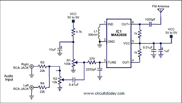
A simple single-chip FM transmitter circuit with a diagram and schematic using the IC MAX 2606, which is a high-performance voltage-controlled oscillator (VCO). The FM transmitter circuit utilizing the MAX 2606 is designed for efficient frequency modulation of audio signals....
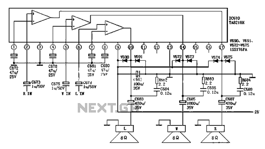
The audio circuit depicted in the figure is commonly utilized in color television systems. The pin functions and reference voltages for the TA8218AH are as follows: Pin 1: 1.9V - inverting input; Pin 2: 2.1V - R-channel audio signal...
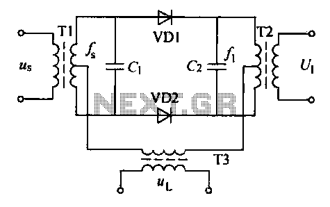
A balanced diode mixer circuit is presented, utilizing two diodes, specifically the 2AP9 model. The circuit operates with a high voltage, causing the diodes to function in an off state, which is also referred to as a diode switch...
Pressing the pushbutton on the transmitter activates a sound and/or light alert in the receiver. This system operates without wiring or radio frequencies; instead, the transmitted signal is conveyed through the mains supply line. It is suitable for use...
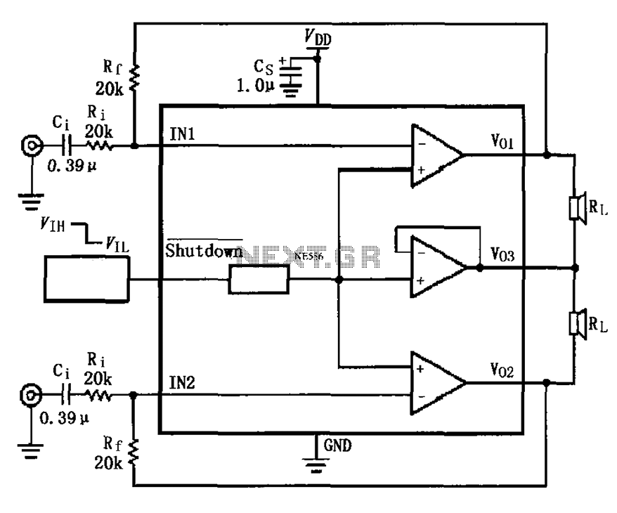
The LM4910 typical circuit is designed for a two-channel amplifier. The left and right channel audio signals are input to the LM4910 (in an MSOP/SO package) at pins 1 and 2. The output signals are delivered from pins 6,...
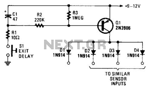
Depressing SI charges CI to the supply voltage. This biases Q1 on via bias resistors R2 and R3. A voltage is available for the duration of the delay period to hold off the alarm circuit. CI can be increased...