
100W Guitar Amplifier 2
The modified schematic presents a refined approach to tone control, enhancing performance through strategic component value adjustments. The tone control circuit now utilizes smaller capacitance values in conjunction with higher resistance potentiometers, which not only reduces costs but also optimizes the circuit's response to audio signals. This configuration is particularly beneficial for achieving a smoother tonal balance without compromising sound quality.
The power amplifier section has undergone significant revisions, likely addressing previous limitations in output fidelity and efficiency. The new design may incorporate improved transistor configurations and feedback mechanisms, contributing to a more robust amplification process. Specific changes in component ratings and types could lead to enhanced thermal performance and lower distortion levels, making the amplifier more suitable for high-fidelity audio applications.
For users seeking a quieter operation, the recommendation to replace the standard op-amp with a 5532 dual op-amp is noteworthy. This component is recognized for its low noise characteristics, which can dramatically reduce background hiss and improve the overall signal-to-noise ratio. While the 5532 may present challenges in terms of availability and cost, its implementation is justified for applications where audio clarity is paramount. Furthermore, adjusting the gain settings by increasing the feedback resistor values can tailor the amplifier's output to meet specific requirements without introducing excess noise, ensuring that the circuit remains versatile for various audio setups.The schematic has been modified slightly to improve the tone control performance (04 Jan 2002). A new schematic is now on line - the differences are relatively minor, but make the component values for the tone controls a bit cheaper (smaller value caps, and higher value pots). The power amp has been heavily revised, and the new version is also available. If a really quiet amp is desired, you should substitute a 5532 dual opamp. These are more expensive (and harder to get), but will offer a substantial noise reduction. If you don`t need all the gain that is available, simply increase the value of the 🔗 External reference
Related Circuits
Simple and low cost. The optimal supply voltage is around 50V, but this amp works from 30 to 60V. The maximal input voltage is around 0.8 - 1V. As you can see, in this design the components have a...
This amp uses the basic circuitry of the 60W power amp but modified for true Class-A operation. This amp has been built by several readers, and the reports I have received have been very positive. With simulations, everything appears...
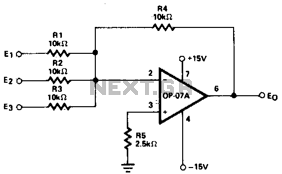
This circuit generates continuous outputs that depend on multiple input variables. The circuit in question typically employs a combination of operational amplifiers (op-amps), resistors, and potentiometers to achieve its functionality. The outputs can be tailored based on the variations...
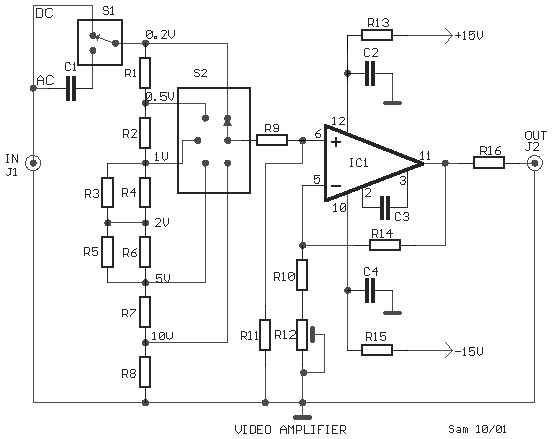
This is a schematic diagram of a video amplifier circuit, built using the very high-speed operational amplifier IC LH0032. Parts List: R1 = 15KΩ, R2, R3, R4 = 10KΩ, R5, R6, R7, R8, R9 = 1KΩ, R10 = 820Ω,...

Sometimes referred to as the JFET µ-amp, this circuit offers a very low power, high gain amplification function. As the drain current decreases, the µ of a JFET increases, meaning that the lower the drain current, the greater the...
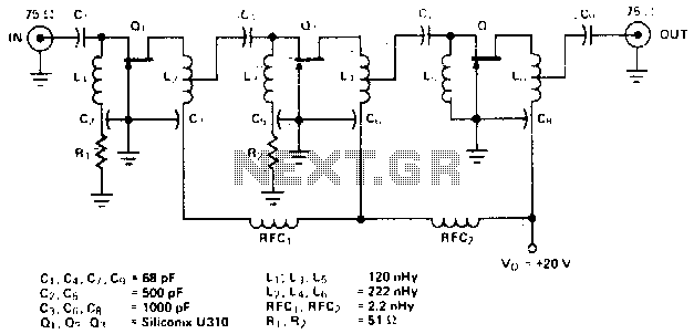
The amplifier circuit is designed for a center frequency of 225 MHz, with a bandwidth of 50 MHz at 1 dB, low input voltage standing wave ratio (VSWR) in a 75-ohm system, and a gain of 24 dB. Three...