
Microphone Voice-Over Circuit
The voice-over unit described is an essential component in audio communication systems, designed to prioritize microphone input over other audio signals when activated. The core of the unit consists of a microphone connected to a preamplifier, which boosts the microphone's signal before it reaches the main amplifier. This preamplifier is crucial for ensuring that the microphone can operate effectively even when placed at a distance from the main amplification system.
The preamplifier circuit utilizes two BC109C transistors, a widely used NPN transistor known for its low noise and high gain characteristics. The first BC109C transistor is configured in a common emitter mode, which is effective for providing high voltage gain. This configuration allows the microphone's low-level audio signal to be amplified significantly. The second BC109C transistor is configured as an emitter follower, which serves to buffer the output of the common emitter stage. This configuration provides a low output impedance, making it ideal for driving subsequent stages of the circuit, such as the LM380 amplifier.
The change-over switch in this design is implemented using a relay with a single changeover contact, which allows for seamless switching between the microphone input and the amplifier's audio signal. When the "push-to-talk" switch is activated, the relay engages, routing the microphone signal to the amplifier while muting other audio inputs. This functionality is critical in environments where clear and prioritized communication is necessary, such as in broadcasting or public speaking scenarios.
The LM380 amplifier serves as the final amplification stage in this circuit, capable of driving speakers or other audio outputs. It is designed to handle significant power levels, making it suitable for a wide range of applications. The overall design requires three wires to connect the remote microphone unit to the amplifier and switching unit, simplifying installation and ensuring reliable operation.
This voice-over unit schematic provides a robust solution for audio applications requiring prioritized microphone input, leveraging the advantages of transistor amplification and relay switching to achieve high-quality audio performance.In its simplest form, a voice-over unit is just a microphone and change-over switch feeding an amplifier, the output from the microphone having priority over the amplifiers audio signal when the "push-to-talk" switch is pressed. In this circuit, a preamplifier immediately follows the microphone and is designed to be used some distance away from the main amplifier.
The changeover switch is nothing more than a relay with a single changeover contact. For completion, an amplifier based on the LM380 is shown. Three wires are needed to connect the remote microphone unit to the amplifier and switching unit. With reference to the above schematic, the two BC109C transistors are used to make a microphone preamplifier. The left hand BC109C operates in common emitter mode, the right hand emitter follower. The combination form a high gain, low output impedance amp 🔗 External reference
Related Circuits
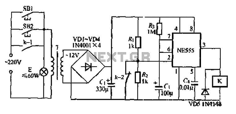
Another application involves the use of a NE555 delay lamp circuit, where components SB1 and SH2 act as J-light buttons that can be installed in two different locations. The lamp can be activated by pressing either SB1 or SB2,...
This project features a schematic for a touch alarm circuit. The circuit is highly sensitive and activates a piezo buzzer or any other type of buzzer, along with an LED, for a predetermined duration when a metal plate is...
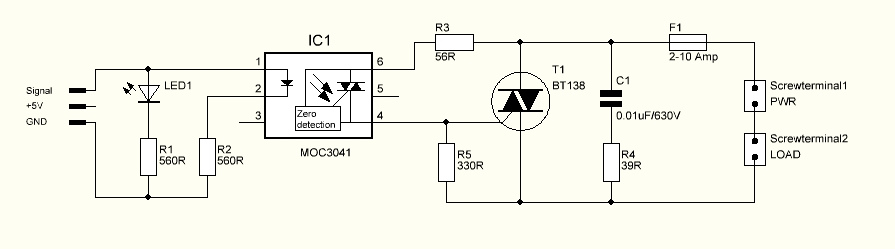
The triac is expected to activate and illuminate the light at nearly 100% brightness; however, it does not turn on at all. If the gate is continuously triggered (i.e., a constant voltage is applied to the gate), the light...

A self-interrupting device connected to a voltage source operates as a switch that continuously opens and closes; thus, the circuit does not latch in the conventional manner, allowing the alarm to function only while switch SI is closed. Due...
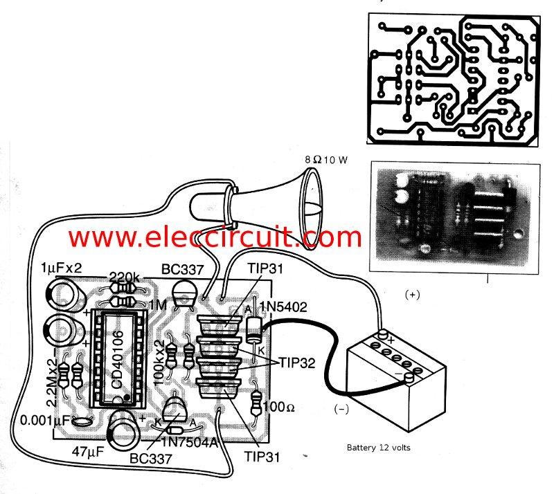
This is a simple siren sound generator with high power output and significant noise. The circuit utilizes digital ICs, specifically the CD4046, in an inverter configuration, along with four transistors to amplify the current output to a horn speaker...
This circuit is designed to detect microwave sources, such as microwave ovens, satellite communication devices, and mobile phones. It provides audio-visual indications upon detecting microwaves in the gigahertz band, which encompasses frequencies between 2 GHz and 300 GHz. Microwave...