
Scr Circuit With Self-Interrupting Load

The described self-interrupting device circuit primarily consists of a switch (SI), an alarm, a silicon-controlled rectifier (SCR), a damping diode (D1), and a resistor (R3) along with the additional 470-ohm resistor for latching functionality. The device operates by maintaining a continuous cycle of opening and closing, which prevents the alarm from latching in a traditional sense. This behavior is crucial for applications requiring temporary alerts or notifications.
The damping diode (D1) serves a critical role in protecting the circuit from voltage spikes generated by the inductive load. When the alarm is triggered, the inductor's collapsing magnetic field can induce a high-voltage spike, which could potentially damage other components within the circuit. The diode provides a path for this induced current, effectively clamping the voltage and safeguarding the SCR and other sensitive elements.
For self-latching operation, the addition of a 470-ohm resistor in parallel with the alarm modifies the circuit's response. When the alarm is activated, the SCR is turned on, allowing current to flow through the alarm and the added resistor. The current through the resistor keeps the SCR in a conductive state even after the initial trigger from switch SI is removed. The value of R3 plays a significant role in determining the minimum current required to keep the SCR latched. If the current falls below this threshold, the SCR will turn off, and the alarm will cease to sound.
To reset the circuit and deactivate the alarm, switch S2 is employed. Pressing S2 allows the anode current to drop to zero, effectively un-latching the SCR. This mechanism is essential for reactivating the alarm system when needed and ensures that the device can be used repeatedly without manual intervention.
Overall, this circuit design offers flexibility in alarm functionality, allowing it to operate in both momentary and latching modes, making it suitable for various applications in alarm systems and safety devices. A self-interrupting device connected to a voltage source functions as a switch that repeatedly open s and closes; therefore, the circuit does not latch in the normal way, so the alarm operates only as long as SI is closed. Because of the inductive nature of that type of load, a damping diode (Dl) must be wired across it. The circuit can be modified to provide a self-latching action simply by wiring a 470- resistor in parallel with the alarm.
The circuit latches because the anode current of the SCR does not fall to zero when the alarm self-interrupts, but to a value that is determined by the value of the R3. The circuit can be unlatched by pressing S2, thereby enabling the anode current to fall to zero when the alarm self-interrupts.
Related Circuits
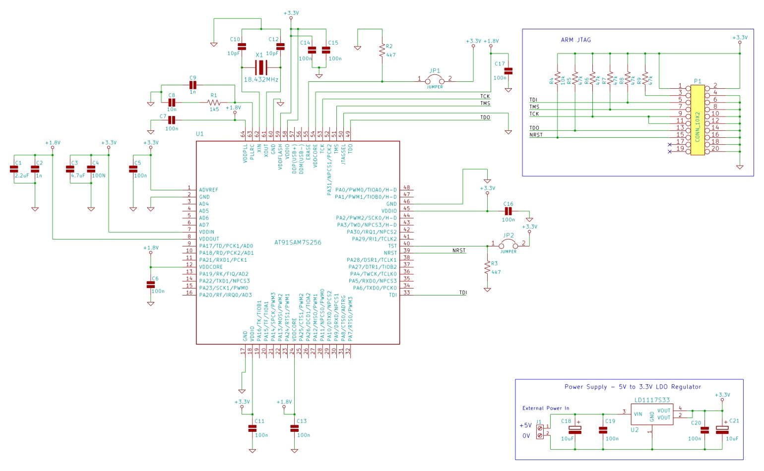
The minimum number of supporting components required to build a circuit using AT91SAM7S microcontrollers. This example uses the AT91SAM7S256 ARM7 microcontroller. To construct a circuit utilizing the AT91SAM7S256 ARM7 microcontroller, a minimal set of supporting components is essential to ensure...
Video-DVM is a very cheap DVM that shows how an output as complex as a videocomposite signal can be generated entirely in software: two I/O pins and three resistors are all the hardware required. Connected to any TV set...
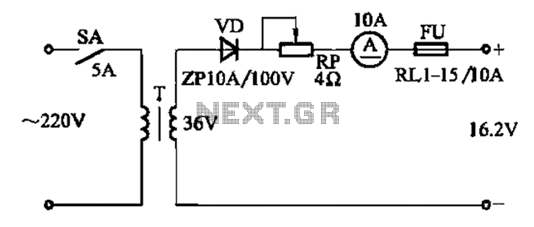
The adjustment potentiometer RP is utilized to modify the charging current. The adjustment potentiometer, designated as RP, serves a critical function in regulating the charging current within an electronic circuit. This component is typically a variable resistor that allows for...
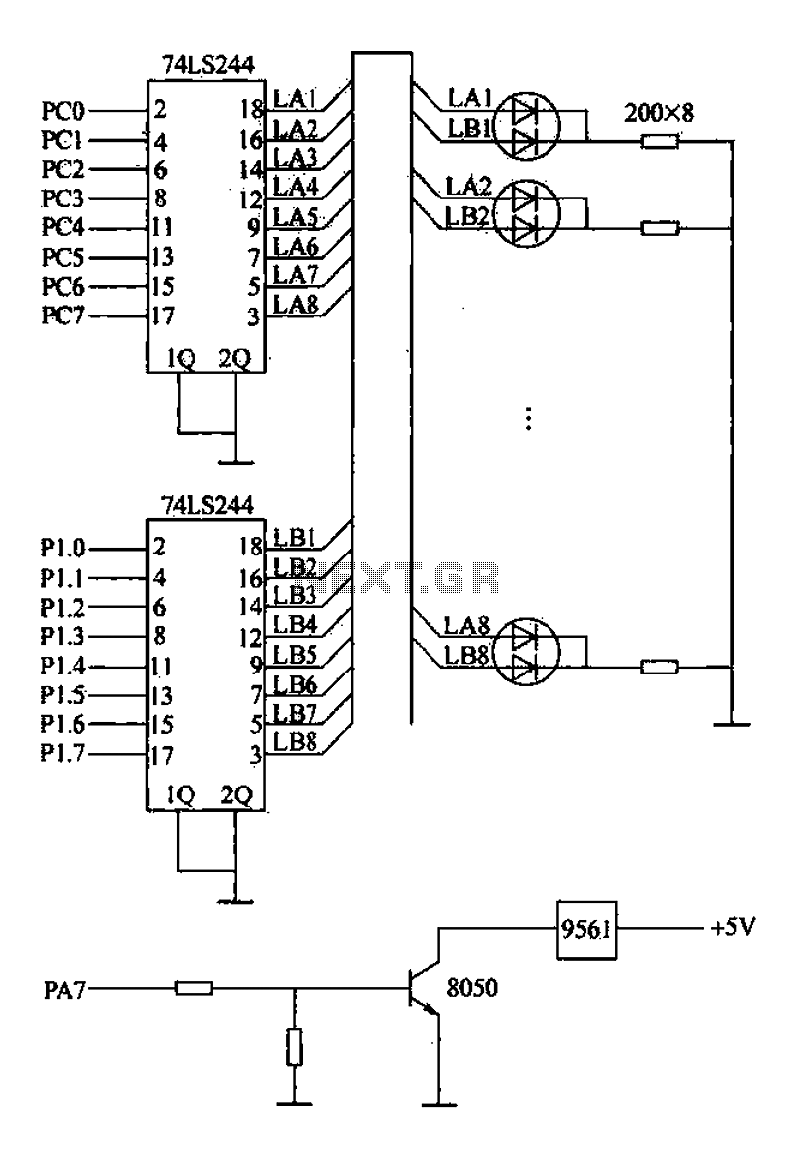
Alarm interface circuitry featuring a two-color light-emitting diode (LED) display. When LAi is at a high level and LBi is low, the green LED lights up; conversely, if LAi is low and LBi is high, the red LED lights...
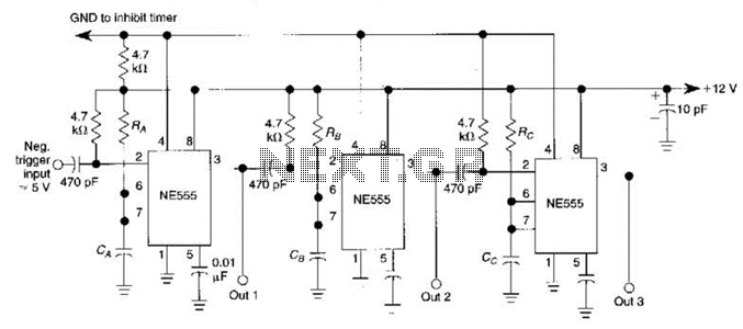
The circuit is designed around a 555 oscillator/timer, providing two distinct time periods. The longer time period can be adjusted between approximately 1 to 10 minutes, while the shorter time period is fixed at around three seconds. The operation...
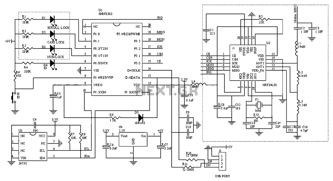
The circuit diagram for the receiving portion of a 2.4 GHz wireless keyboard is presented below. The 2.4 GHz wireless keyboard receiving circuit typically consists of several key components that work together to receive and process signals transmitted from the...