
touch alarm circuit

The touch alarm circuit is designed to detect physical contact with a metal plate, which serves as the sensing element. The core component of the circuit is a sensitive touch sensor, which can be implemented using various technologies such as capacitive sensing or resistive touch detection. When a user touches the metal plate, the sensor detects the change in capacitance or resistance, triggering the subsequent actions in the circuit.
Upon activation, the circuit energizes a piezo buzzer, producing an audible alert. The LED indicator illuminates simultaneously, providing a visual cue that the alarm has been triggered. The duration for which the buzzer and LED remain active can be controlled by a timing circuit, often implemented using a resistor-capacitor (RC) network or a dedicated timer IC such as the 555 timer. This allows for customization of the alarm duration based on the specific application requirements.
Power supply considerations are also crucial for the circuit's operation. The circuit can be powered using a battery or a regulated DC power supply, ensuring that the components receive the appropriate voltage and current levels for reliable performance. Additionally, the inclusion of a debounce circuit may be necessary to prevent false triggering due to noise or unintended touches.
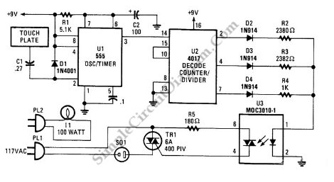
Overall, the touch alarm circuit is a practical and versatile project that can be utilized in various applications, such as security systems, notification alerts, or interactive installations. Its simplicity and effectiveness make it an excellent choice for both hobbyists and professionals in the electronics field.Here is a very interesting project / schematic of a touch alarm circuit. The circuit is quite sensitive and it will activate a peizo or any other buzzer and an LED for a set time period when any one touches the metal plate.. 🔗 External reference
Related Circuits
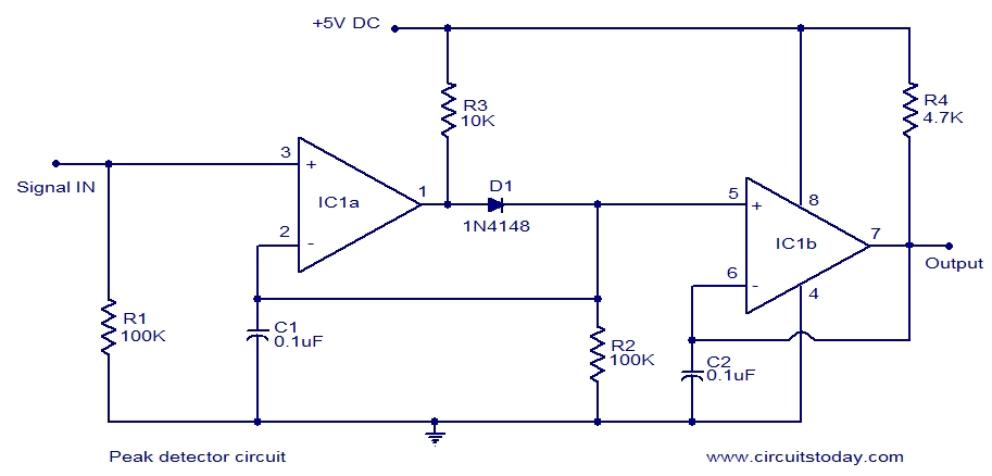
LM339-based peak detector circuit. Simple and easy to construct. Operates from a 5V DC single supply. LM339 is a dual comparator. The LM339-based peak detector circuit is designed to capture and hold the peak value of an input signal. This...
This is a classic design of a 35 W final amplifier utilizing two EL34 tubes in a push-pull configuration, developed by Siemens and Halske. The design dates back to March 24, 1953, and is identified by the code SV410/1....
The RF power amplifier circuit described here utilizes the transistors 2SC1970 and 2N4427. This FM RF amplifier operates within the frequency range of 88-108 MHz, delivering an output power of approximately 1.3W from an input driver of 30-50mW. The...

A simple audio amplifier can be designed using the LM380 along with a few external components. This amplifier features a wide supply voltage range, an input impedance of 150 kΩ, low distortion, and a current capability of 1.3 A. The...
This is a three-mode lamp dimmer circuit with touch control. This circuit can be used to control a lamp in three operation modes: dim, off, and bright. A NE555 timer is utilized in the design. The three-mode lamp dimmer circuit...
The Mark3 version of the Infrared extender is specifically designed to control appliances that utilize high-frequency modulated infrared remote signals. The Mark3 Infrared extender functions as a bridge between a standard infrared remote control and appliances that operate with high-frequency...