
Auto Ignition Cut-Off

This anti-theft circuit employs an SCR and relay arrangement to enhance vehicle security. The SCR functions as a controlled switch, which remains in the off state until a positive voltage is applied to its gate. When the gate receives the necessary voltage, the SCR allows current to flow, energizing the relay. The relay, once activated, closes its contacts, thereby allowing the ignition circuit to complete and the vehicle to start.
The implementation of this circuit requires careful consideration of the SCR's specifications, including its voltage and current ratings, to ensure it can handle the demands of the ignition system. The relay should also be selected based on its capacity to manage the ignition load, typically rated for automotive applications.
To enhance security, the positive voltage required to trigger the SCR can be sourced from a hidden switch or an accessory that is not commonly used. This makes it difficult for potential thieves to bypass the system, as they would need to locate and activate the hidden switch to enable the ignition.
Wiring the circuit involves connecting the SCR in series with the relay coil and the ignition system. The gate of the SCR is connected to the hidden switch or accessory, which provides the necessary voltage when activated. Proper insulation and routing of wires is essential to prevent tampering and ensure reliability.
In summary, this SCR and relay combination circuit serves as an effective anti-theft measure by preventing unauthorized vehicle operation. It is crucial to incorporate reliable components and ensure secure installation to maximize the effectiveness of the system. Using an SCR/relay combination, this circuit can be made to cut off ignition, unless a positive voltage is applied to Hhe gate of the SCR. This is useful as an anti-theft device, because depending on hook-up, the car will not start unless a certain accessory or a hidden switch is closed.
Related Circuits
Automatic gain control. A control circuit that automatically changes the gain (amplification) of a receiver. Automatic Gain Control (AGC) is a crucial circuit used in various electronic devices to maintain a consistent output level despite variations in input signal strength....
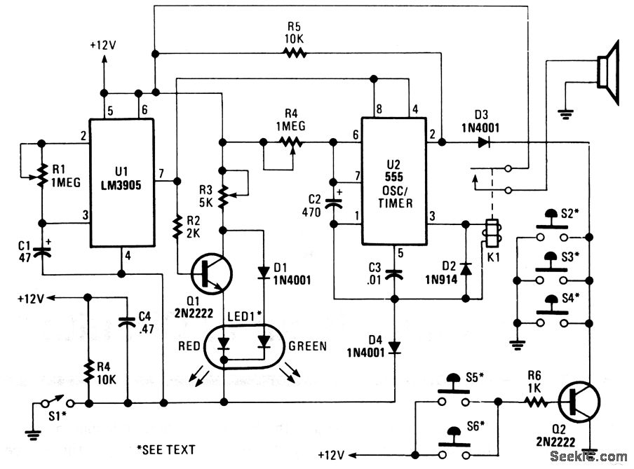
The alarm circuit is designed to provide a time delay of 0-47 seconds, which is determined by the combination of resistor R1 and capacitor C1. This delay allows the vehicle's motion sensor to stabilize after the switch is armed,...
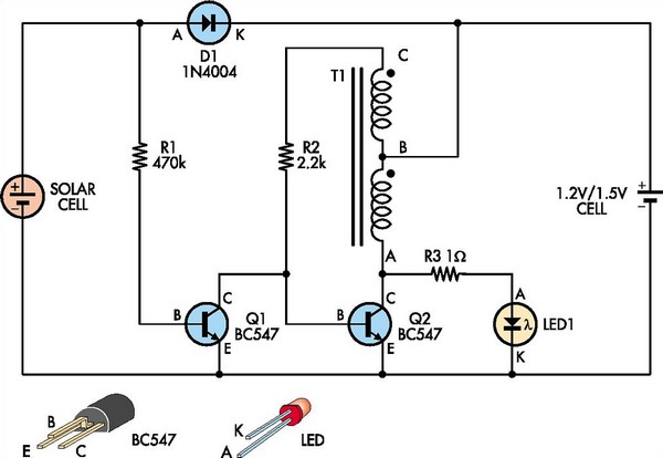
This white LED driver circuit is suitable for garden lighting applications. It automatically activates the LED at night and operates from a single 1.2V NiCad cell, which is recharged by a solar cell during the day. The prototype utilized...
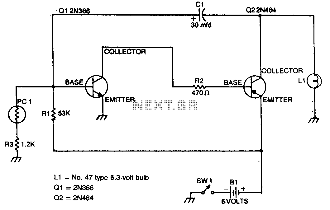
This flasher activates only during nighttime, providing bright illumination and automatically turning off when sunlight is detected. The photocell should be positioned on top of the unit to maximize light detection. The circuit for the nighttime flasher utilizes a photocell...

This transistor ignition circuit enhances vehicle starting and ensures smoother engine operation, especially at both high and low RPMs. It contributes to lower fuel consumption, reduced emissions, and decreased maintenance costs. The system promotes economical and electronic driving. The transistor...
This is the primary component of the home automation system. The objective was to create a circuit board that can be customized for various functions by selectively populating the board, adding daughter boards, and modifying the software. Currently, this...