
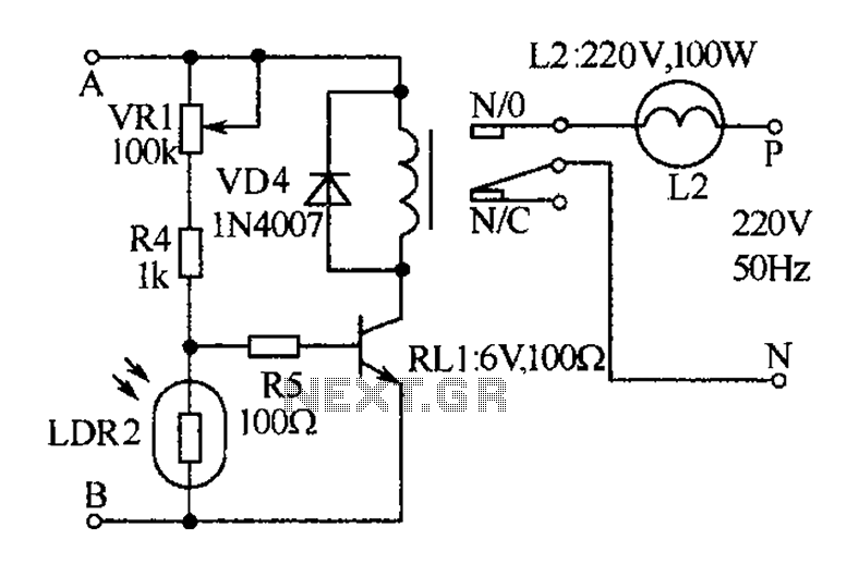
Auto light controller

The circuit utilizes a 555 timer IC configured in monostable mode, which is ideal for generating a single output pulse when triggered. The input to the timer is derived from the photoresistors, which serve as light sensors. When ambient light levels are low, the resistance of the photoresistors is high, preventing the timer from triggering. However, when headlights shine on the photoresistors, their resistance drops significantly, allowing a voltage level sufficient to trigger the 555 timer.
The timing interval is determined by the values of the resistor (R) and capacitor (C) connected to the timer. The time period (T) for which the output remains high can be calculated using the formula T = 1.1 * R * C. In this circuit, the chosen R-C values are designed to achieve an approximate duration of two minutes, ensuring that the lights remain on for a sufficient period after being triggered.
Relay RY1 acts as a switch, controlling the power to the lights. When the timer output goes high, it energizes the relay coil, closing the contacts and allowing current to flow to the lights. Once the timer elapses and the output returns to low, the relay is deactivated, opening the contacts and turning the lights off.
This setup is particularly useful in automotive applications where lights need to be activated automatically in response to external light conditions, enhancing safety and convenience. The positioning of the photoresistors at headlight height ensures optimal sensitivity to oncoming vehicles, allowing for timely activation of the lights. The automatic shut-off feature prevents unnecessary battery drain, making the circuit efficient and practical for real-world use.A 555 timer IC, operating in the one-shot mode, is triggered by light striking photoresistors. These normally have a resistance of several megohms but, in the presence of light, that resistance drops to several hundred ohms, permitting current from the six-volt source to flow in the circuit. The R-C combination shown gives an on-time of about two minutes. Photoresistors PC3 and PC4 are mounted at heatlight-height. When headlights illuminate the photoresistor, the timer starts. That actuates a relay, RY1, and the lights are turned on. The lights are automatically turned off when the timer's two minutes are up.
Related Circuits
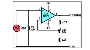
This circuit demonstrates the utilization of a standard LED as a light sensor. It leverages the photovoltaic voltage generated across the LED when exposed to light. The circuit operates on the principle that an LED can function as a photodiode,...
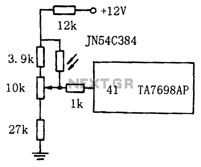
The circuit for automatic brightness adjustment in a television utilizes a photosensitive resistor and a contrast potentiometer connected to an intermediate stage. The photosensitive resistor varies its resistance based on light intensity, causing changes in the potential at the...
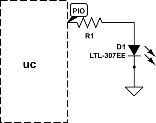
The LED will illuminate when the PIO (Programmable Input/Output) pin goes low, functioning similarly to a ground connection. In this configuration, the current is sourced from the power supply rather than the PIO, as in the first method. It...
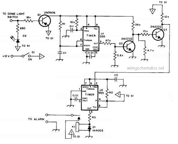
This circuit diagram represents a smart car alarm timer. This design is more advanced compared to traditional car alarm systems. When activated, the alarm remains active for 80 seconds, following an initial delay of 15 seconds. The smart car alarm...

This circuit controls a searchlight-type signal head and produces solid red, yellow, or green indications. The signals can be connected for normal or approach-type lighting of the green signal. The circuit utilizes an LM556 dual timer IC in a...
The receiver, as depicted in the figure, assists patients in avoiding missed audio signals during the daytime. The receiver operates independently, and the lighting will automatically turn off. At night, the lighting signal receiver activates simultaneously with the patient's...