
Auto poweroff for power supplies circuit


The described circuit utilizes relay logic for automatic switching, employing a relay identified as RL1, which contains a coil and two sets of contacts. The operation begins with a momentary push switch (Sw1). When Sw1 is activated, it closes its contacts, allowing input voltage (In) to energize the relay coil. This energizing action causes RL1/1 to close, directing power to the output (Out), while RL1/2 simultaneously shorts Sw1, ensuring that the relay coil remains powered even after the switch is released. This configuration establishes a bistable state, meaning the circuit can maintain either an 'on' or 'off' state without continuous input from Sw1.
The circuit also reflects a common arrangement found in 4QD controllers, characterized by a switched current source that feeds a zener diode, which serves as a voltage stabilizer. The current flowing through the zener diode is monitored by a transistor that controls the current source. This mechanism is crucial for preventing overload conditions; if the output voltage rises excessively, causing the zener current to drop to zero, the circuit will automatically disconnect, thereby protecting the system.
Additionally, the circuit can be adapted to function as a bistable regulator. In this setup, the series pass transistor operates as a current source, although this configuration is not mandatory. The zener diode is connected to the emitter of the pass transistor, with a resistor in place to regulate the current supplied to the transistor. This arrangement allows the transistor to adjust its conduction in response to variations in output voltage, maintaining stability. The current source also serves as a current limiter, which can be optionally removed if not required for specific applications.
Overall, this relay-based switching mechanism and the associated current regulation strategy provide a robust solution for managing power in electronic circuits, ensuring reliability and efficiency in operation.Probably the easiest way of doing automatic switch off is with relay logic. In the diagram, the box marked RL1 is the coil, the 2 in the coil box tells you there are two sets of contacts somewhere on the circuit, operated by this coil. In this simple circuit, it's easy to see them!Sw1 is a momentary push switch. When it's pushed (contacts closed), voltage from In is applied to the coil so the relay operates. RL1/1 (the first set of contacts on RL1) closes and applies power to Out. RL1/2 closes at the same time and shorts out Sw1, maintaining power to the relay coil. So Sw1 is a push to switch on and the circuit is a relay bistable - bistable as it has two stable states, on and off.
There are lots of ways of doing this type of switching and the diagram below shows but one This system is the way many of 4QD's controllers are powered, though this particular circuit is most like that of the 4QD series. It is essentially a switched current source feeding a zener diode which acts as a stabilizer. The current though the zener is monitored by one of the transistors that switches the current source so that as the output voltage gets overloaded (so that the zener current falls to zero) the circuit switches itself off.
There is more information including a discussion and component values in the 4QD-TEC members area page. There is an article on site on two transistor regulator circuits. The third of these circuits is a bistable regulator. As often happens when thinking of one circuit, another idea pops into mind. The switching on and off arrangement in the above circuit can also apply to this regulator, and the circuit below illustrates this idea.
As in the above circuit, the series pass transistor is arranged as a current source: this is not always necessary. The regulating zener is here returned to the emitter of the transistor, which has a resistor present.
This shuts off the current fed to the series pass transistor so that it conducts a variable amount to maintain the output voltage. The current source is then a current limit (which is why it can, optionally, be removed. 🔗 External reference
Related Circuits
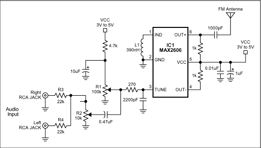
A simple FM transmitter connects a home entertainment system to a portable radio that can be moved around the house and into the backyard. For instance, music can be played from a CD player in the living room and...
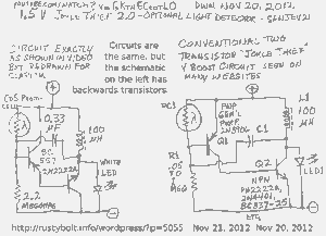
A schematic of a two-transistor Joule Thief was presented in a YouTube video by Sanjev21, which has since been removed. The two-transistor Joule Thief is a compact and efficient circuit designed to extract energy from low-voltage sources, such as depleted...
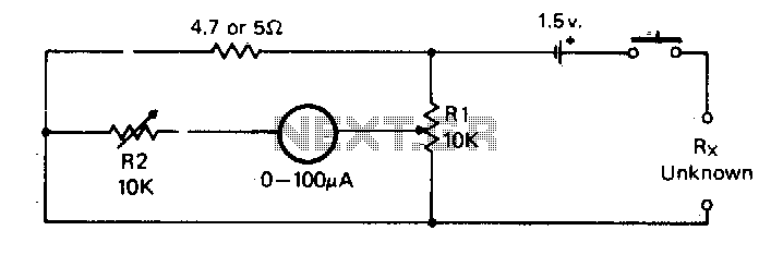
For the measurement of resistances ranging from approximately 5 ohms down to about 0.1 ohm. This circuit is highly practical. The described circuit is designed to measure low resistances with high precision, specifically in the range from 5 ohms down...
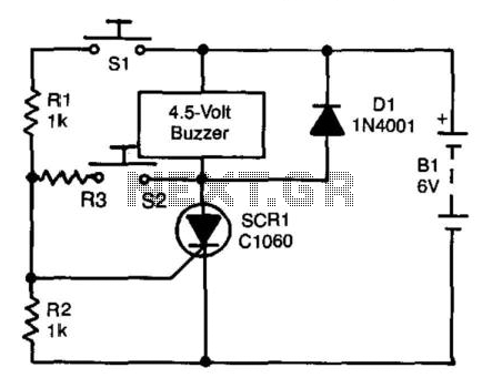
A self-interrupting device connected to a voltage source operates as a switch that continuously opens and closes; thus, the circuit does not latch in the conventional manner, allowing the alarm to function only while switch SI is closed. Due...
This circuit is designed for rapid battery charging. It is recommended for those who require a faster charger. The charger operates at a low temperature of 5 degrees Celsius. The input voltage is 15 volts DC, while the output...

In battery-powered applications in which power management is key, a microprocessor may adjust its core voltage corresponding to an increase or a decrease in clock speed, allowing full processing power when necessary but not wasting excess power when idle....