
Storage Battery Exerciser

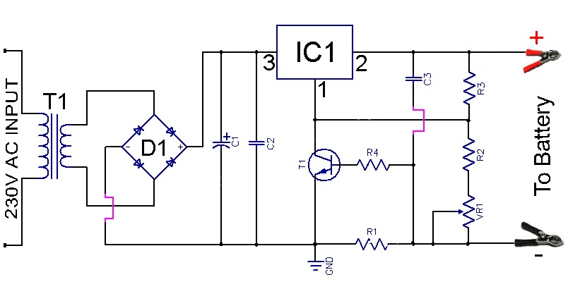
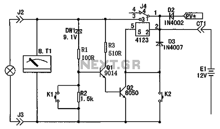
IC1.A functions as an astable multivibrator with an asymmetric duty cycle, outputting a high signal for approximately 0.6 seconds and a low signal for about 40 seconds. IC1.B is configured as a comparator that continuously monitors the battery voltage, with its threshold set to 11.0 V using a trimpot. When the battery voltage falls below this threshold, the comparator outputs a low signal, which cuts off D6, allowing the second astable multivibrator, IC1.C, to oscillate at approximately 1.2 Hz. This causes LED D7 to blink, indicating that the battery requires charging. As long as the battery voltage remains above 11 V, IC1.B outputs a high signal, keeping IC1.A low for the majority of the time. In this state, D4 conducts, resulting in the inverting input of IC1.D being low, which keeps IC1.D high most of the time, ensuring T1 remains cut off. T1 only conducts during the 0.6-second intervals when IC1.A is high, allowing current to flow through a 12 V / 3 W lamp, which serves as the load for the battery. Following this, the circuit remains inactive for 40 seconds. The average current consumption of the circuit is approximately 5 mA, which means a relatively new 40-Ah battery would take about one year to fully discharge under these conditions. However, variations in battery condition may necessitate periodic recharging during the winter months.
The circuit's design effectively addresses the issue of battery maintenance during periods of inactivity by utilizing a combination of astable multivibrators and a comparator to regulate charging and discharging cycles. The use of a trimpot for voltage threshold adjustment provides flexibility in monitoring different battery types and conditions. The blinking LED serves as a clear visual indicator of the battery's status, ensuring that users are alerted when recharging is necessary. The overall low power consumption of the circuit allows for prolonged battery life, making it an efficient solution for maintaining battery health during extended storage. The inclusion of a load in the form of a lamp simulates normal usage patterns, further aiding in the prevention of sulfation and other issues associated with battery dormancy. Overall, this circuit represents a practical approach to battery management, ensuring that stored batteries remain in optimal condition until they are needed again.A motorcycle or boat battery that is not needed over the winter is usually charged before being put away for the winter, after which it remains standing unused for months on end. As a result, it accumulates deposits of lead sludge, which can result in reduced capacity or even complete failure of the battery.
If you don`t keep active, you rust! To avoid this, it`s necessary to keep the battery active even during the winter. This circuit does such a good job of exercising the battery that it doesn`t have to be recharged during the winter. It only has to be fully charged again in the spring before being used again. IC1. A is an astable multivibrator with an asymmetric duty cycle. The output is High for around 0. 6 s and Low for around 40 s. IC1. B is wired as a comparator that constantly monitors the battery voltage. Its threshold voltage is set to 11. 0 V using the trimpot. As soon as the battery voltage drops below this value, the comparator goes Low and D6 is cut off, allowing the second astable multivibrator IC1.
C to oscillate at approximately 1. 2 Hz. LED D7 then blinks to indicate that the battery must be charged. As long as the battery voltage is greater than 11 V, IC1. B is High. IC1. A is Low most of the time, and in this state D4 conducts and the inverting input of IC1. D is Low. This means that IC1. D is High most of the time, with T1 cut off. T1 only conducts during the 0. 6-s intervals when IC1. A is High. In this state it allows current to pass through the lamp (12 V / 3 W), which forms the actual load for the battery. After this, darkness prevails again for 40 s. The average current consumption is approximately 5 mA. At this rate, a relatively new 40-Ah battery will take around one year to become fully discharged. However, this can vary depending on the condition of the battery, and it may be necessary to top up` the battery once during the winter.
🔗 External reference
Related Circuits
NiCd battery charger schematic and description. This NiCd battery charger circuit can charge 12V, 6V, and 9V battery packs. The NiCd battery charger circuit is designed to efficiently charge nickel-cadmium (NiCd) batteries, specifically those with voltage ratings of 12V, 6V,...
The LM7805 circuitry used in the Harbor Freight 42292 charger has been replaced with an LM317 variable voltage regulator. This change was likely made for cost reduction or to address supply issues. The original design included a variable resistor,...
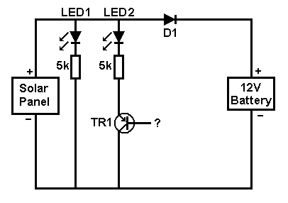
A small solar panel is used to maintain a 12V car battery. The panel provides approximately 75mA of current to the battery under full sunlight conditions. The described circuit employs a solar panel specifically designed for battery maintenance applications. The...
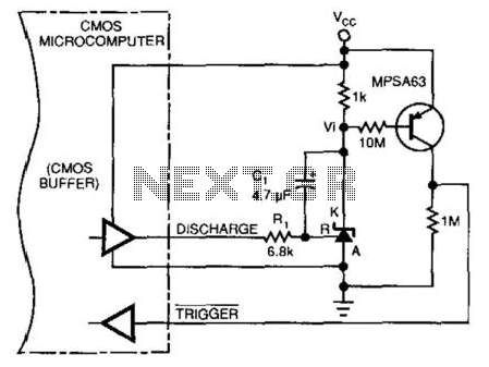
This circuit enables a microprocessor system to measure its own battery voltage. A Texas Instruments TI43 precision shunt regulator functions as a precise reference and integrator/amplifier, measuring its own supply through voltage-dependent charge and discharge time intervals. It is...
The charger's output voltage is adjustable and regulated, featuring an adjustable constant-current charging circuit that facilitates compatibility with most NiCad batteries. It is capable of charging a single cell or multiple series-connected cells, with a maximum voltage of 18...
The circuit depicted in the figure consists of a battery, a controller, and various electrical and charging components. It includes a Zener diode (D1) and resistors (R1, R2) for undervoltage detection. The circuit also features transistors (Q1, Q2), resistors...