
Automated Attendant burglar alarm circuit

The automatic unattended burglar alarm circuit is designed for effective intrusion detection in various environments. The primary component, the pyroelectric infrared sensor, detects motion based on changes in infrared radiation, which is emitted by warm bodies, such as humans. The sensor's output is connected to an integrated circuit (IC1), which serves as the processing unit for the alarm system.
The light control circuit is critical to the operation of the alarm system, as it prevents false alarms during the day. The photoresistor RG is strategically placed to monitor ambient light levels. When the light intensity exceeds a certain threshold, RG's resistance drops, allowing current to flow through the base of transistor VT1, which subsequently turns on and short-circuits the alarm circuit, preventing it from activating during daylight hours.
At nighttime, the resistance of RG increases significantly, causing transistor VT1 to turn off. This transition prepares the circuit to enter an alert state. The pyroelectric infrared sensor remains vigilant, constantly monitoring for any movement within its detection range. If an intruder is detected, the sensor sends a signal to IC1, which activates the alarm driving circuit (IC2). This circuit typically includes a buzzer or siren, which emits a loud sound to deter the intruder and alert nearby individuals.
For optimal performance, the circuit may include additional components such as capacitors for filtering noise, diodes for reverse polarity protection, and possibly a power supply circuit to ensure stable operation. The overall design emphasizes reliability and ease of installation, making it suitable for both residential and commercial applications.It shows an automatic unattended burglar alarm circuit, mainly for family night, warehouses and other occasions automatic unattended. The circuit consists of pyroelectric infrared sensor light control circuit (RG, RP2, R4), the alarm driving circuit (IC2 and foreign components) , and the like. At higher light intensity during the day, low resistance state photoresistor RG, the transistor is turned on VTI, the alarm circuit shorted: In the night -RG resistance value becomes larger, VT1 off, ready to enter the stage alarm circuit alarm state, when someone enters the pyroelectric infrared sensor probe measured area, ICI foot is triggered, the buzzer alarm.
Related Circuits
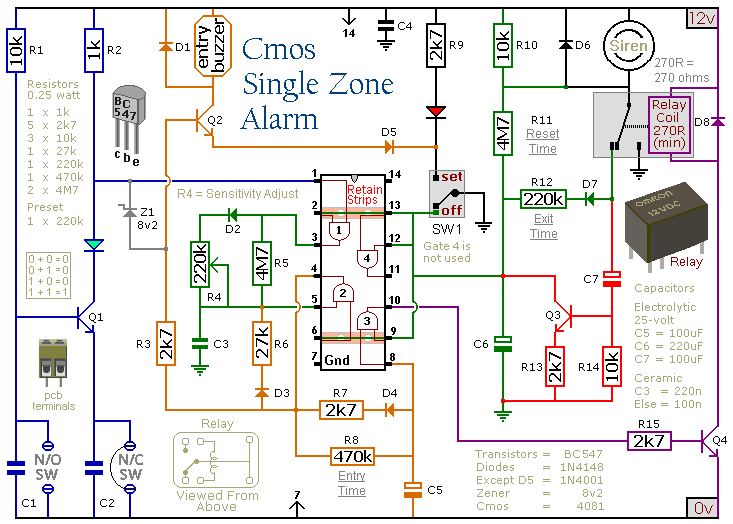
This circuit features automatic exit and entry delays, a timed bell cut-off, and a system reset. It accommodates both normally-open and normally-closed switches, making it compatible with various input devices such as pressure mats, magnetic reed contacts, foil tape,...
When light strikes the Light Dependent Resistor (LDR), its resistance decreases significantly. The voltage at the junction of the LDR and resistor R2 gradually charges capacitor C2 through resistor R1. After approximately 10 seconds, the voltage across the capacitor...

This simple Christmas LED lights decoration circuit allows for the creation of an 18 LED flasher to adorn a Christmas tree. The circuit incorporates white, blue, and red LEDs that flash in a festive pattern. The circuit is designed to...

This network wiring tester consists of two components: a transmitter unit, which is powered and installed at the network's starting point, and a passive receiver unit that can be moved from socket to socket. Both units contain eight LEDs,...

A popular project among microcontroller enthusiasts is to build a radio-controlled clock. Tiny receiver boards are available, equipped with a pre-tuned ferrite antenna that receives and demodulates the DCF77 time signal broadcast from Mainflingen in Germany. DCF77 has an...

This circuit utilizes three readily available 555 timer integrated circuits (ICs), all functioning as astable multivibrators. The first 555 timer has both an on period and an off period of 1 second. This IC regulates the on/off intervals of...