
automatic aquarium feeder

No description available.
Related Circuits
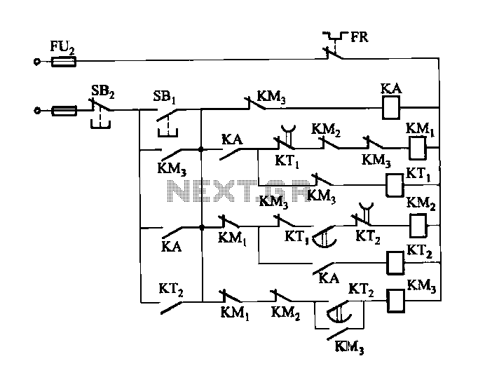
Figure 3-118 illustrates an automatic acceleration control circuit. This circuit employs a male contactor time relay, enabling the motor to start automatically at a low speed before transitioning to high-speed operation. The automatic acceleration control circuit depicted in Figure 3-118...
This light-sensitive automatic light switch circuit is designed to be connected to the main 220V supply. The circuit will activate a 220V lamp during nighttime. The light-sensitive automatic light switch circuit operates by utilizing a light-dependent resistor (LDR) to detect...

The circuit utilizes the Trigger and Threshold pins (2 and 6) to monitor maximum and minimum voltage levels. Two voltage comparator operational amplifiers within the 555 timer manage the output state, switching it on or off. The Trigger pin...
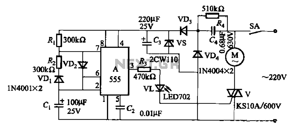
The circuit depicted in Figure 3-16 utilizes a 555 IC (Integrated Circuit) as the control element. It features a capacitive step-down circuit and incorporates a bidirectional thyristor (V) for intermittent motor control operation. By adjusting the resistance values of...
R2 must be adjusted to establish the correct finish charge voltage. Flooded and gel batteries are typically charged to 13.8V. For cycling batteries, such as AGM or gel types, battery manufacturers generally recommend a voltage range of 14.5V to...
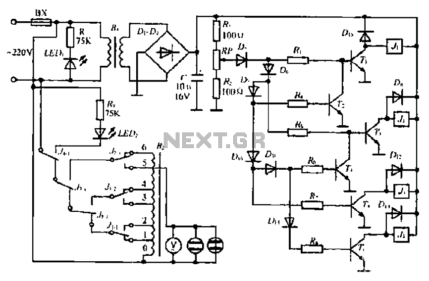
A step-down transformer converts AC 220V to a lower voltage. A diode bridge rectifier and filter capacitor provide a direct current (DC) output, which fluctuates with variations in the grid voltage. A resistive voltage divider is used for sampling....