
Simple Burglar Alarm

The alarm circuit is designed for simplicity and effectiveness, employing a single IC to manage the logic and control functions. The choice between NO and NC sensors provides flexibility in application, allowing the circuit to be tailored to specific security needs.
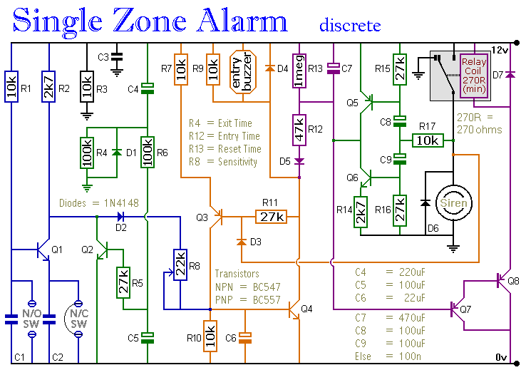
The integrated circuit (IC) serves as the central processing unit of the alarm system. U1A, U1B, and U1C are likely different sections of the IC, performing various logic functions. When a sensor is activated, it sends a low signal to U1A, initiating a sequence of events. U1A's output goes high, which might indicate the alarm state, while U1B's low output could serve as a reset or standby signal. U1C’s high output likely indicates that the relay should be activated.
Transistor Q1 acts as a switch that controls the relay K1. When Q1 is biased ON by the high output from U1C, it allows current to flow through the relay coil, thus closing the relay contacts. This action can trigger an external alarm or notification system. The use of a relay provides an effective means of controlling higher power devices or systems that require isolation from the low-power control circuit.
The inclusion of keyswitch S1 allows the user to manually turn the alarm system on or off. This feature is essential for maintenance or when the system needs to be temporarily disabled without disconnecting power.
Overall, this alarm circuit design is efficient and straightforward, making it suitable for various applications where monitoring and alerting are necessary. The use of commonly available components ensures ease of assembly and maintenance. Using one IC and a driver transistor, this simple alarm uses either NO or NC sensors. When a sensor operates, the inpu t to U1A goes low, causing U1A to go high, U1B low, and U1C high. This biases Q1 ON and activates relay Kl. On/off is via keyswitch SI.
Related Circuits
The circuit incorporates automatic exit and entry delays, a timed bell cut-off, and a system reset feature. It accommodates both normally-open and normally-closed switches and is compatible with standard input devices such as pressure mats, magnetic reed contacts, foil...

The circuit serves as a foundational design, requiring experimentation for specific applications. In popular microwave bands, local oscillators (LOs) are typically generated using overtone crystal oscillators followed by multipliers. A table presents the standard LO frequencies for narrowband segments,...
This simple circuit is sure to have the police beating a path to your door - however, it has the added advantage of alerting you to their presence even before their footsteps fall on the doormat. The circuit transmits...

This simple circuit can be utilized to activate various devices, such as connecting it to microcontrollers, relays, secret alarms, or robot applications. It can also be used to turn on LED1, which remains lit as long as the metal...

Removing R1 or R2 from the circuit allows a potential thief to break a hidden wire that connects R1 to +12 V and R2 to ground. This action activates the alarm for approximately five minutes. The circuit in question is...
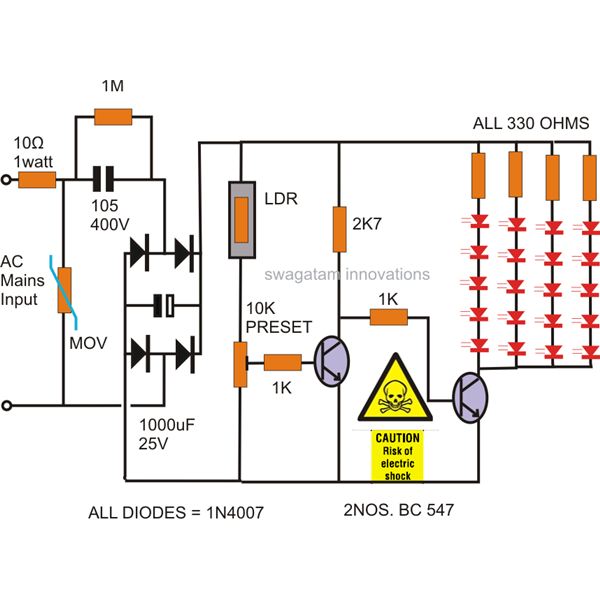
The power supply utilized in this circuit is of the capacitive type, eliminating the need for a transformer and allowing for a compact design that can be easily installed in small spaces. The circuit employs LEDs instead of traditional...