
Automatic emergency lighting circuit

The automatic emergency lighting circuit is designed to provide reliable illumination during power outages, making it an essential addition to any household. The circuit begins with the connection to the 220V AC mains supply, where capacitor C1 plays a crucial role in voltage reduction, ensuring that the subsequent components receive a manageable voltage level.
The half-wave rectifier, composed of diode VD1 and capacitor C2, converts the AC voltage to a pulsating DC voltage. This filtered output is used to charge the battery, which serves as the backup power source during an outage. The charging current, approximately 90mA, is sufficient for maintaining the battery's charge while the mains is operational.
Transistor VT1 acts as a control switch in the circuit. When the mains power is available, VT1 is forward-biased, allowing current to flow and keeping transistor VT2 off. This state ensures that the emergency light (EL) remains off during normal operation, thus conserving battery power.
In the event of a power failure, VT1 ceases to conduct, which triggers VT2 to turn on, allowing current to flow to the EL bulb. This transition is critical for providing immediate illumination when it is most needed. Diode VD2 functions as a protective element, preventing backflow of current from the battery to the base of VT1, thereby ensuring that the circuit operates safely and effectively.
When the mains power is restored, VT1 resumes conduction, which turns off VT2 and extinguishes the EL bulb, resetting the system for future use. The circuit is designed to operate efficiently with a small load, making it suitable for use with either four 1.5V batteries in series or a single 6V battery, providing flexibility in power source selection.
Overall, the design emphasizes simplicity, cost-effectiveness, and reliability, making it an ideal choice for emergency lighting solutions in residential settings. The use of readily available components further enhances its accessibility for DIY enthusiasts and families looking to enhance their home safety measures.Automatic emergency lighting circuit shown, it is suitable for families install yourself. Because it uses smaller components, the price is cheaper. When the normal power supply mains, 220V AC mains voltage through capacitor CI ire.k pressure, and then by a half-wave rectifier diode VD1 and capacitor C2, after filtering, pulse current of about 90mA to charge the battery. And this at the same time, since the transistors VT1 base with a forward bias state in the conduction state, so that a 2 is off, the bulb does not light EL..
Once the mains power network, turned on by the transistor VT1 goes off, VT2 off by the change to the conduction, EL light bulb. Diode VD2 role is to isolate the battery and VT1 base level, to ensure that electricity stops. VT1 turn HU indigo only. After mains power is restored, VT1 conduction, EI. Off, reset the circuit. Figure. To 6. 3V, 0.15A small electric startled, batteries can be used 4 1 battery, can also be used 6V batteries.
Related Circuits
Electron trajectories in a conductor are depicted in the diagrams below. When no electric field is present inside a conducting material, electrons move randomly. However, when an electric field is applied, the electric force F = qE induces a...
Figure 14-41 illustrates a multivibrator circuit utilizing a 555 timer alongside various capacitive and resistive components. The oscillation frequency is determined by the values of Ra, R16, and C3, following the formula f = 1.44 / ((Ra + 2R16)...
Several individuals have mentioned that the house number is difficult to read at night. The number comprises four digits mounted on a structural column that supports a section of the roof. In response to these concerns, a request has...
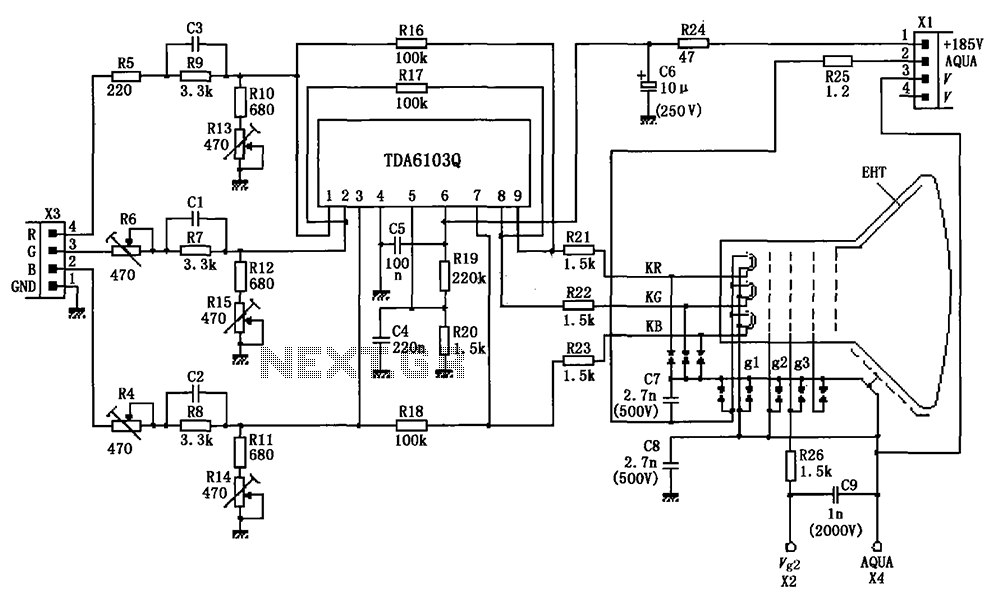
The circuit depicted in the figure integrates the TDA6103Q with a color picture tube, illustrating its practical application. The red, green, and blue (R, G, B) input signals are received from the input socket X3 and processed through a...
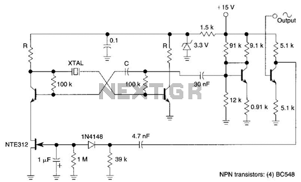
Q1, Q2, and the associated circuitry constitute a modified astable multivibrator where the loop gain is automatically adjusted to the threshold of oscillation by field effect transistor Q3. Q4 amplifies the signal at the collector of Q2 and isolates...
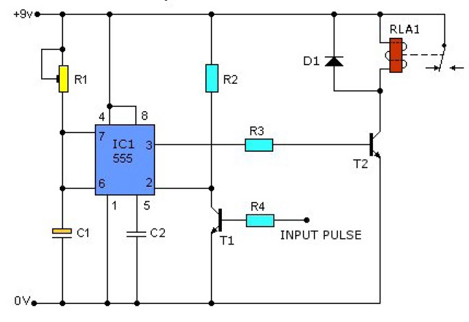
This causes T1 to conduct, pulling pin 2 of IC1 low. IC1 then enters a timing cycle, the duration of which is set by R1 and C1, resulting in pin 3 of IC1 going high. This action causes T2...