
By the actual application circuit composed of a color picture tube with TDA6103Q

The TDA6103Q is a versatile RGB amplifier designed for driving color picture tubes. In this configuration, the input signals are conditioned through a resistor-capacitor network to ensure proper signal levels and frequency response before amplification. The output stage of the TDA6103Q provides the necessary drive currents to the cathodes of the color picture tube, where the emitted electrons interact with the phosphor coating on the inside of the tube to produce visible images.
The use of resistors R21, R22, and R23 is critical for controlling the current flowing to each cathode, allowing for precise color balance and intensity adjustments. The potentiometers included in the circuit offer a means to fine-tune the white balance, ensuring that the colors displayed on the screen are accurate and consistent. The careful selection of these components is essential for achieving optimal performance and maintaining image quality.
The protection against high-voltage discharge is a crucial aspect of this design, as it safeguards the TDA6103Q from potential damage due to electrical breakdown. This protective feature is particularly important in applications where high voltages are present, as it enhances the reliability and longevity of the circuit.
Overall, this schematic showcases a well-engineered solution for driving a color picture tube, emphasizing the importance of component selection, signal processing, and protective measures in high-voltage electronic applications. As shown in FIG grounds TDA6103Q and color picture tube composed of the actual application. R, G, B input signal from the input socket X3, through the input resistor network co nsists of capacitors into the TDA6103Q 1,2,3 feet, respectively, from the amplified signal output pin 9,8,7, through R21, R22, R23 is added to the color picture tube three cathodes KR, KG, KB, cathode emission electrons produce images. TDA6103Q supply voltage is provided by socket X1 pin 1 + 185V input voltage applied to TDA6103Q 6 feet.
Enter the network potentiometer R13, R6, R15, R4, R14 for the white balance adjustment potentiometer. Color picture tube cathode and the gate using protected forms gap discharge, the output of the amplifier to protect TDA6103Q internal breakdown will not be generated when the high pressure discharge between the electrodes.
Related Circuits
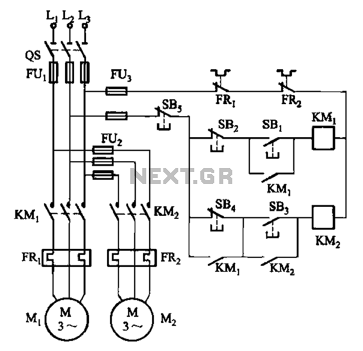
The circuit depicted in Figure 3-84 allows two electric motors to be started independently. The motors can only be activated after pressing the main stop button (SBz) to release contact KMi. Following this, the auxiliary stop button (SB4) can...
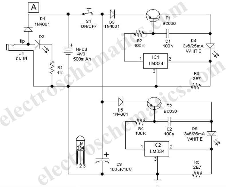
This easy-to-construct handy pen torch electronic circuit has a low component count and utilizes two power white LEDs for illumination. A low voltage (4.8V DC) supply is derived from a built-in rechargeable Ni-Cd battery pack and is converted into...
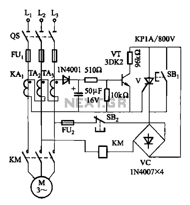
Both circuits are used to control the thyristor contactor KM action to overcome the break phase protection relay prone to malfunction or refuse to move, and enhance the sensitivity and reliability of the protection device. The described circuits are designed...
The following circuit illustrates the SCR BRY35 used in a simple radio control circuit. Features include a straightforward and efficient receiver for operation. The SCR BRY35 is a silicon-controlled rectifier designed to facilitate the control of high-power loads through low-power...
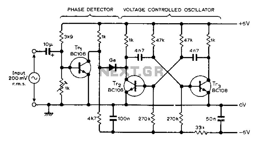
The circuit MVBR utilizes a traditional two-transistor configuration along with other components to create a simple phase-locked loop (PLL). The transistor TR1 and diodes function as a logic gate, activating during half periods of the input waveform of the...
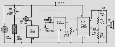
When there is no smoke, the light from the bulb directly illuminates the Light Dependent Resistor (LDR). In this condition, the resistance of the LDR is low, resulting in a voltage drop of less than 6V across it. Consequently,...