
Regulated dual power supply circuit

The regulated dual power supply circuit is designed to convert the alternating current (AC) from the mains into two stable direct current (DC) voltages, specifically +12V and -12V. This functionality is crucial for various electronic applications, particularly in experimental setups and testing environments.
The circuit begins with transformer T1, which is responsible for stepping down the high voltage AC mains to a lower voltage suitable for further processing. The transformer’s secondary winding outputs an AC voltage that is subsequently rectified by diodes D1 through D4, configured in a full-wave bridge rectifier arrangement. This configuration ensures that both halves of the AC waveform are utilized, improving efficiency and providing a smoother DC output.
Following rectification, capacitors C1 and C2 are employed to filter the pulsating DC voltage produced by the diodes. These capacitors charge during the peaks of the rectified waveform and discharge during the troughs, effectively smoothing out the voltage to reduce ripple. The values of these capacitors are selected based on the load current and the desired ripple voltage.
Decoupling capacitors C3, C4, C7, and C8 are strategically placed within the circuit to stabilize the voltage levels and suppress high-frequency noise that may be present in the power supply. These capacitors ensure that the voltage remains constant under varying load conditions, which is vital for sensitive electronic components.
The voltage regulation is achieved through the integration of linear voltage regulators IC 7812 and IC 7912. The 7812 regulator is designed to output a stable +12V, while the 7912 regulates the output to -12V. Each regulator includes internal protection features such as thermal shutdown and current limiting, which enhance the reliability of the power supply.
The outputs of the regulators are typically connected to additional filtering capacitors to further smooth the output voltage and provide a stable power source for connected loads. This dual power supply configuration is widely used in op-amp circuits, analog signal processing, and other applications requiring dual polarity voltage sources. Overall, this circuit design exemplifies a robust solution for providing regulated dual outputs from an AC source, essential for a variety of electronic projects.The circuit given here is of a regulated dual power supply that provides +12V and -12V from the AC mains. A power supply like this is a very essential tool on the work bench of an electronic hobbyist. The transformer T1 steps down the AC mains voltage and diodes D1, D2, D3 and D4 does the job of rectification.
Capacitors C1 and C2 does the job of filtering. C3, C4, C7and C8 are decoupling capacitors. IC 7812 and 7912 are used for the purpose of voltage regulation in which the former is a positive 12V regulator and later is a negative 12V regulator. The output of 7812 will be +12V and that of 7912 will be -12V. 🔗 External reference
Related Circuits
The CDI ignition circuit generates a spark from an ignition coil by discharging a capacitor across the primary winding of the coil. A 2µF capacitor is charged to approximately 340 volts, with the discharge process controlled by a silicon-controlled...
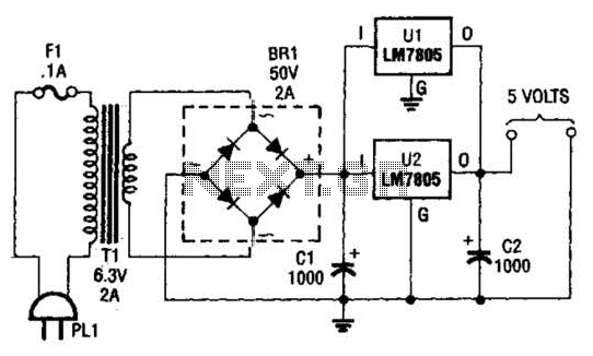
This DC supply is excellent for operating battery-powered antique radios, as it is designed to prevent damage to the tube filaments. The circuit is useful for powering the filaments of 00-A, 01-A, 112A, and 71A tubes, which require 5V...
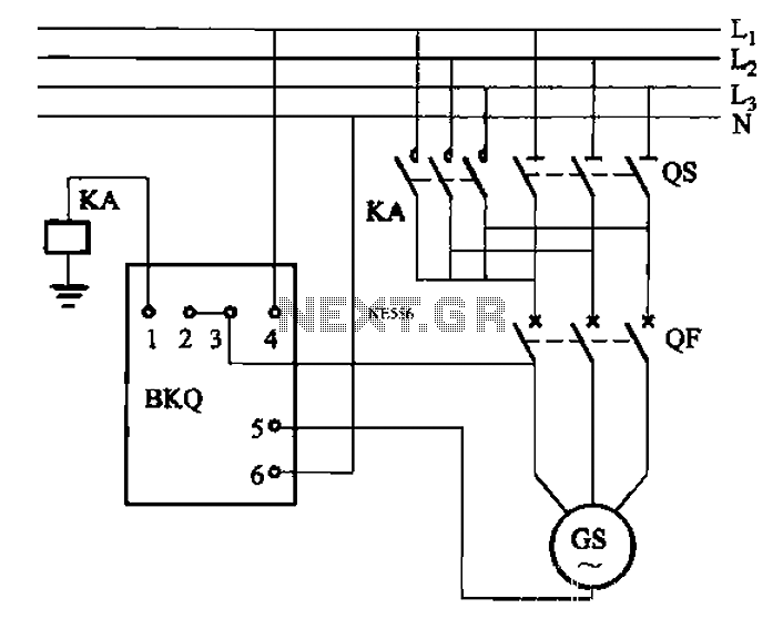
BKQ series automatic parallel controllers are specifically designed for small hydropower automation devices operating in parallel, with a capacity of 3200 kW and below, for both high and low pressure turbines. These controllers automatically adjust based on the generator...
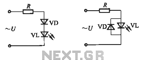
Light-emitting diodes (LEDs) can be powered using direct current (DC), alternating current (AC), and pulse drivers. A typical buck LED display circuit is illustrated in Figure 13-1. The current-limiting resistor (R) for LED tubes can be calculated using the...
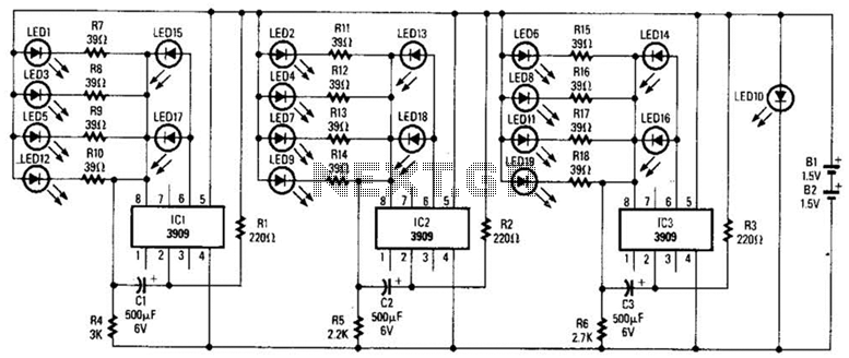
Three individual flashing circuits utilizing an LM3909 LED flasher/oscillator IC create the illusion of a pseudo-random firing order. The capacitors CX1, CX2, and CX3 control the blink rate, which ranges from 0.3 to 0.8 seconds. The wide tolerance range...

This design circuit is for audio graphic equalizers, which are commonly found in commercial products, yet circuits for them are rarely published. The circuit features a simple design that requires an operational amplifier (op-amp) to amplify the input signal....