
circuit How to find currents of all nodes using superposition theorem

The superposition theorem is a fundamental principle in circuit analysis that allows for the simplification of complex circuits by considering the contribution of each independent source separately. In this context, the circuit under analysis contains three nodes, and the goal is to find the currents at these nodes by applying the superposition theorem effectively.
To begin, each independent source in the circuit should be analyzed one at a time. When examining the effect of a voltage source, all other voltage sources must be replaced with short circuits, while current sources are replaced with open circuits. For example, when analyzing the source associated with V1, the circuit should be modified accordingly to isolate its effects. The calculated current through V1, referred to as i_1, reflects the influence of this source alone.
After determining the current contributions from each source, the next step involves summing these individual currents at each node. This approach allows for the accurate calculation of total current flowing through the circuit when all sources are considered simultaneously. It is crucial to maintain awareness of current directions during this process. Current direction can be denoted using arrows, with the understanding that if the actual current flows contrary to the drawn arrow, it will yield a negative value in the final analysis.
To enhance understanding, it is recommended to include a schematic diagram of the circuit, clearly labeling each node and current direction. This visual representation will facilitate comprehension of the circuit behavior and the application of the superposition theorem, making it easier to track currents and validate calculations. By following these steps, a comprehensive analysis of the circuit can be achieved, ensuring all currents are accounted for and accurately represented.Using the superposition theorem, I need to find the current of all the 3 nodes of the circuit. Using superposition I`ve found that the current from the source: Do you mean i_1 is the current through V1 when the other voltage sources are shorted out, in line with the first step of solving the problem with super position Davorak Mar 6 `13 at 21 :51 @Davorak: Yes! The 2nd one is exactly what I mean. I`ve shorted it out finally, I hadn`t calculated all the other currents at the nodes when I was applying superposition. I did now, and all the currents are correct. Chris Mar 6 `13 at 23:28 After you have solved the circuit for each source individually you can add together the currents of each branch to get the total current of the final circuit with all sources.
I it is not possible, with out solving the circuit in some fashion to know the directions of current you are taking about in your questions. It would be a good idea to include a diagram like on fo the below or add an up/down, left/right annotation to your current where appropriate.
You can draw your current arrows in any direction you want, if the current is actually flowing in the opposite direction of your arrow then then it will just end up being a negative current in your solution. 🔗 External reference
Related Circuits

The TDA1519 circuit can deliver 2x6 watts output power. TDA1519 is an integrated class-B dual output amplifier in a 9-lead single in-line (SIL) plastic medium power package primarily developed for car radio applications. The TDA1519 is a robust integrated circuit...
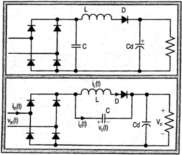
The input current for a passive power factor correction (PFC) circuit is not affected by variations in the output ripple, resulting in the need for a smaller inductance compared to earlier circuit designs. Passive power factor correction circuits are utilized...
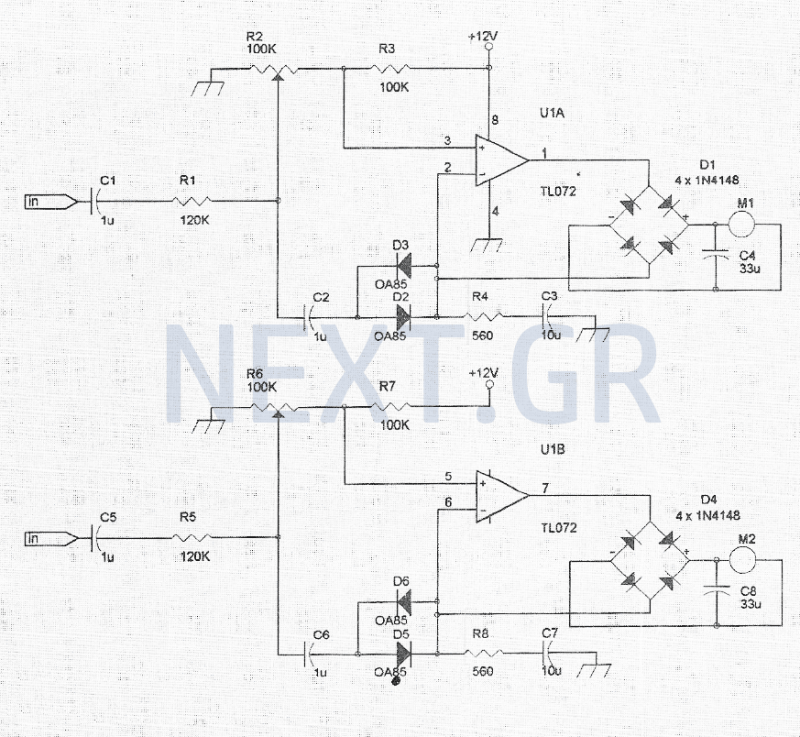
The VU meter is categorized into two types: those that use needle instruments and those that employ LED columns. A VU meter sound level meter is essential for both tube amplifiers and integrated amplifiers. Currently, there are numerous integrated...
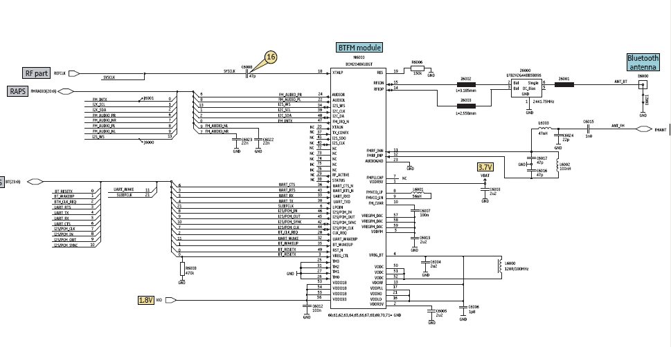
Bluetooth is an open wireless technology standard for exchanging data over short distances between fixed and mobile devices, utilizing short wavelength radio transmissions to create personal area networks (PANs) with high security. The Bluetooth baseband protocol combines circuit and...
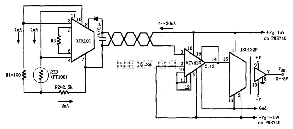
The circuit comprises an isolated RTD loop current configuration utilizing the XTR101 for transmitting loop current and the RCV420 for receiving it. The instrumentation amplifier detects changes in temperature via a resistance temperature detector (RTD), converting these changes into...
Power amplifier circuit diagram using the IC TLE2141C. The TLE2141C is a low-noise, high-voltage, high-slew-rate operational amplifier with a frequency response of 30 Hz. The TLE2141C operational amplifier is designed for applications requiring high precision and low noise, making it...