
automatic laser poweroff circuit

The automatic laser power-off circuit is designed to enhance safety and efficiency in laser applications by ensuring that the laser system can be deactivated automatically under certain conditions. The circuit typically includes a power supply, control logic, and a visual indicator, such as an LED, to signal the operational status of the laser.
The schematic includes a power source connected to a control unit that monitors specific parameters, such as temperature or beam alignment. When the system detects an anomaly, the control unit sends a signal to a relay or transistor that interrupts the power supply to the laser, effectively shutting it down.
The visible power indication is provided by an LED that illuminates when the circuit is active, indicating that the laser is powered on and operational. Conversely, when the laser is turned off, the LED will extinguish, providing a clear visual cue that the system is in a safe state.
Ground connections are critical in this circuit to ensure stability and prevent noise interference. The schematic should clearly mark the ground reference points, which are essential for proper circuit operation. The design may also include additional components such as resistors and capacitors for filtering and stability, as well as protection diodes to safeguard against voltage spikes.
In summary, this automatic laser power-off circuit schematic is an essential tool for maintaining safety in laser operations, providing both automatic shutdown capabilities and clear visual indicators for user awareness.Here`s the Automatic Laser poweroff circuit schematic. This circuit provides a visible power indication. In this case, Ground is waiting on one side.. 🔗 External reference
Related Circuits
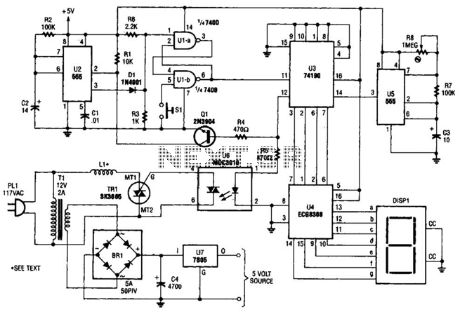
The electromagnetic ring launcher consists of four subcircuits: a clock circuit utilizing U5, a 555 oscillator/timer configured for astable operation; a countdown/display circuit incorporating U3, a 74190 synchronous up/down counter with BCD outputs set for countdown operation; U4, an...
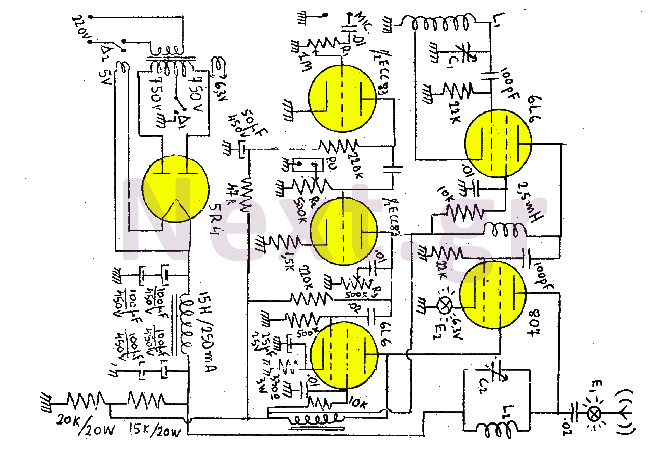
This transmitter consists of a total of five bulbs. The 6L6 tube functions as an oscillator, directing oscillations to the grid of the 807 tube, which serves as the final amplifier and the transmitter output lamp. The amplifier includes...
The LM1036 is a DC-controlled circuit designed for tone adjustment (bass/treble), volume control, and balance. It is suitable for use in car radios, televisions, and audio systems. The circuit also incorporates loudness compensation. The LM1036 integrates several functionalities essential for...
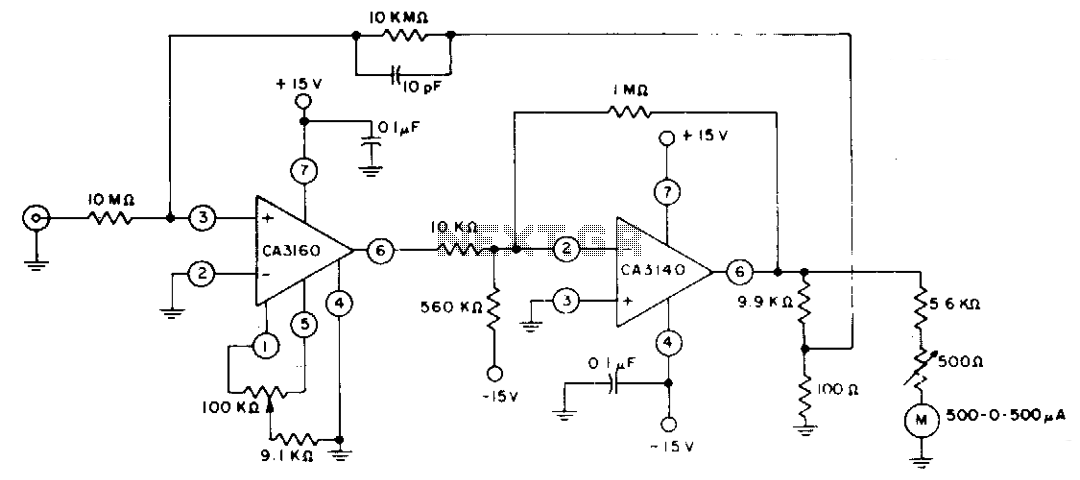
The circuit employs CA3160 and CA3140 BiMOS operational amplifiers to achieve a full-scale meter deflection of ±3 pA. The CA3140 functions as a 1T0 gain stage, supplying the necessary positive and negative output swing for the meter and the...
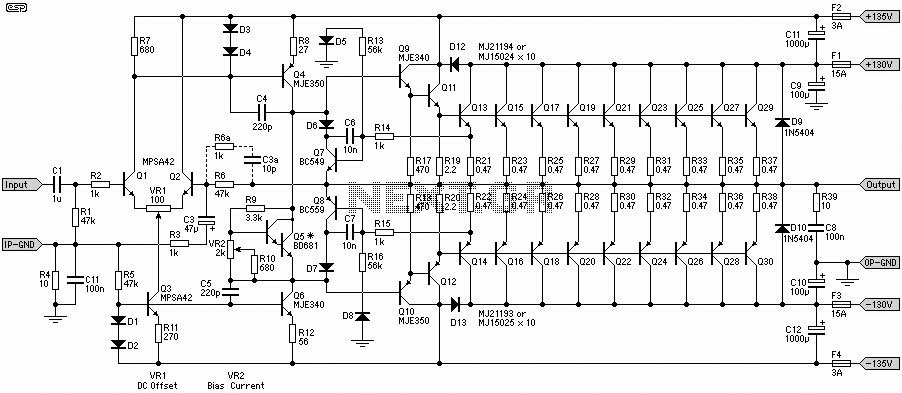
This 1500W Power Amplifier Circuit Diagram contains two images of the circuit. For more complete information, refer to the main post titled "1500 Watt Power Amplifier." It includes a list of component parts for the 1500W Power Amplifier Circuit...
You may be familiar with this effect. You switch audio equipment such as an amplifier to a different input and there is a loud click or "thump" in the speaker system. Not all equipment is affected. Some high-end audio...