
digital thermometer or talk I2C to your atmel microcontroller

The I2C bus operates using a simple protocol that allows for efficient communication between devices. The master device controls the timing and sequence of data transmission, ensuring that each slave device responds appropriately to requests. The two lines, SDA and SCL, are actively managed through pull-up resistors that maintain a high state when not being driven low by a device. This configuration allows for multiple devices to share the same bus without interference, as each device can be uniquely addressed by the master.
In practical applications, the I2C protocol is particularly advantageous in scenarios where minimal data transfer is required, such as sensor readings or configuration settings. The simplicity of the two-wire connection reduces the complexity and size of the circuit, making it an ideal choice for compact designs. Furthermore, the inherent flexibility of the I2C protocol allows for easy expansion, enabling additional slave devices to be added to the bus without significant redesign.
The implementation of I2C communication in microcontroller-based projects can significantly streamline the design process, reduce component count, and enhance reliability. By leveraging this efficient communication protocol, engineers can develop robust systems that meet the demands of modern electronic applications.A pre-requisite for this article is that you have the GCC AVR programming environment installed as described in my "Programming the AVR microcontroller with GCC, libc 1. 0. 4" article. If you want to avoid troubles with the installation you can of course use the AVR programming CD from When you use such an advanced device as a microcontroller
to measure analog or digital signals then you want of course interfaces to evaluate the data or send commands to the microcontroller. In all the articles presented here in the past we always used rs232 communication with the UART that is included in the microcontroller.
The problem is that this requires an additional MAX232 chip and 4 extra capacitors. Atmel suggests also that an external crystal osciallator is required for the UART communication to work reliably. In any case it is a lot of extra parts. and we can avoid them! The amount of data to transfer between PC and microcontroller is usually very small (just a few bytes).
Speed it therefore no issue at all. This makes the I2C bus/protocol suitable for this task. I2C (prounouce "eye-square-see") is a two-wire bidirectional communication interface. It was invented by Philips and they have protected this name. This is why other manufacturers use a different name for the same protocol. Atmel calls I2C "two wire interface" (TWI). Many of you might already be using I2C on their PCs without knowing it. All modern motherboards have an I2C bus to read temperatures, fan speed, information about available memory. all kind of hardware information. This I2C bus is unfortunately not available on the outside of the PC (there is no physical connector).
Therefore we will have to invent something new. The datasheet of the Atmega8 (see references) has actually a very detailed description starting on page 160. I will therefore present here just an overview. After this overview you will be able to understand the description in the datasheet. On the I2C bus you always have one master and one or several slave devices. The master is the device that initiates the communication and controls the clock. The two wires of this bus are called SDA (data line) and SCL (clock line). Each of the devices on the bus must be powered independently (same as with traditional rs232 communication).
The two lines of the bus are normally connected via 4. 7K pullup resistors to logically "High" (+5V for 5V ICs). This gives an electrical "or" connection between all the devices. A device just puls a line to GND when it wants to transmit a 0 or leaves it "High" when it sends a 1. The master starts a communication by sending a pattern called "start condition" and then addresses the device it wants to talk to.
Each device on the bus has a 7 bit unique address. After that the master sends a bit which indicates if it wants to read or write data. The slave will now acknowledge that it has understood the master by sending an ack-bit. In other words we have now seen 9 bits of data on the bus (7 address bits + read_bit + ack-bit): Next we can receive or transmit data. Data is always a multiple of 8 bits (1 byte) and must be acknowledged by an ack-bit. In other words we will always see 9-bit packets on the bus. When the communication is over then the master must transmit a "stop condition". In other words the master must know how much data will come when it reads data from a slave. This is however not a problem since you can transmit this information inside the user protocol. We will e. g use the zero byte at the end of a string to indicate that there is no more data. SDA H - /- /- /- L -/ -/ -/ -. SCL H - /- /- /- /- /- L -/ -/ -/ -/ -/ -. | START | 1 | 1 | 0 | 1 | 0 | One of the best things about this protocol is that you do not need a precise and
🔗 External reference
Related Circuits

It may be easy to find a precision voltage reference for your application; however, a programmable precision reference is another matter. The circuit in Figure 1 yields a precision reference with an LSB of 62.5 µV. The circuit is...
The PIC16F84A digital thermometer circuit is constructed primarily using a temperature sensor along with various discrete components. The PIC16F84A microcontroller serves as the core processing unit of the digital thermometer circuit. It is equipped with an 8-bit architecture and supports...
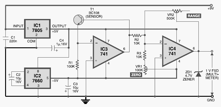
This digital thermometer circuit diagram uses a common 1N4148 diode as the temperature sensor. The temperature coefficient of the diode is -2 mV/°C. The digital thermometer circuit leverages the characteristics of the 1N4148 diode, which has a well-defined temperature coefficient....
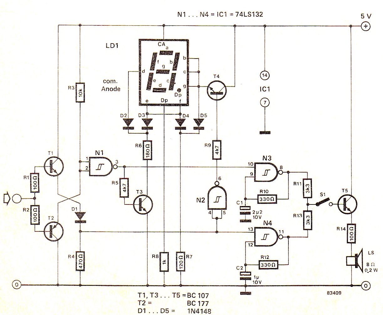
When the input signal is at logic high (1), the display indicates `H`, and the loudspeaker emits a note that is one octave higher than the low tone. The operation of the circuit can be observed in the circuit...
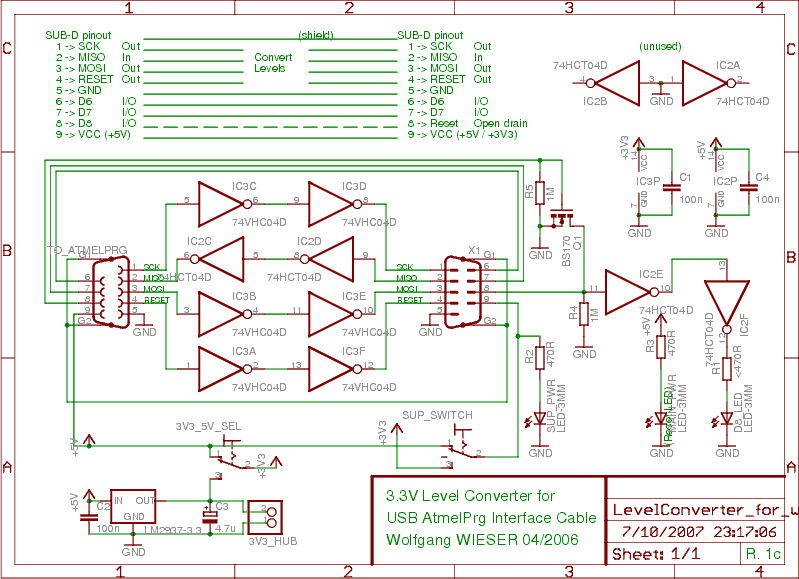
To program devices operating at 3.3V, such as SPI-based AVRs or JTAG-based CPLDs, level conversion is necessary for input and output signal levels. A 5V input may not register as HIGH at 3.3V, and a 3.3V device can be...
Inquiry regarding the circuit design involving ICs 4029N and 4511N, specifically questioning whether these components function as a driver/decoder. The datasheet was consulted but did not provide precise specifications. The IC 4029N is a binary up/down counter that can count...