
Traffic-light application in C language (AVR-007)
")
The project focuses on developing a traffic-light control system using the AVR-007 microcontroller. The AVR-007 is a versatile microcontroller that offers multiple input and output pins, allowing for efficient control of various components such as LEDs, sensors, and switches. A fundamental understanding of the microcontroller's architecture, including its pin configuration, memory allocation, and peripheral interfaces, is crucial for successful implementation.
The traffic-light application will involve programming the microcontroller to manage the timing and sequencing of the traffic lights. The typical traffic light consists of three colored LEDs: red, yellow, and green. Each LED will be connected to a designated output pin on the AVR-007. The microcontroller will be programmed to turn on each LED for a specified duration, simulating real-world traffic light behavior.
To begin, the hardware setup will require the following components: the AVR-007 microcontroller, three LEDs (red, yellow, and green), current-limiting resistors for the LEDs, a breadboard for prototyping, and jumper wires for connections. The LEDs should be connected to the output pins of the microcontroller with the appropriate resistors to prevent excessive current flow.
The programming aspect will involve writing code in a suitable language, such as C or assembly, that instructs the microcontroller to control the LEDs based on defined timing intervals. The code will include initialization routines, where the pins connected to the LEDs are configured as outputs. A loop will be created to cycle through the states of the LEDs, ensuring that the red light is displayed for a longer duration, followed by the yellow and green lights.
Testing the circuit will involve verifying the correct operation of each LED according to the programmed timing. Adjustments may be made to the timing intervals based on practical observations to achieve the desired traffic control functionality.
Overall, this project serves as an excellent introduction to microcontroller programming and hardware interfacing, providing hands-on experience in creating a functional traffic-light control system.learn to use microcontrollers to create traffic-light applications. In this project we will use microcontroller AVR-007 from Circuits-Home. Before creating the program, the first job we have to do is understand about the hardware specs. 🔗 External reference
Related Circuits
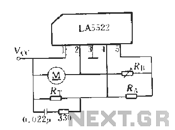
LA5522 Application Circuit. It operates as follows: When the supply voltage (Vcc) changes due to mechanical loads or negative changes, the motor speed may vary. The speed is proportional to the anti-electric potential (E), which also causes changes in...
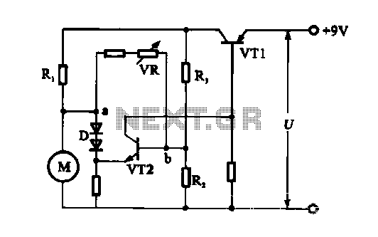
The electronic circuit for steady speed motor applications utilizes an automatic remote control system to regulate the motor power supply, thereby achieving consistent speed control. The circuit diagram illustrates a DC motor connected to the system. Given that the...
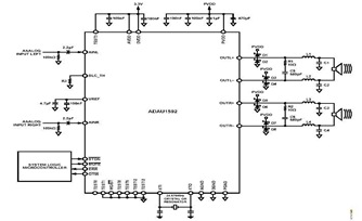
This is a typical stereo application circuit schematic of the ADAU1592, a 2-channel, bridge-tied load (BTL) switching audio power amplifier. The ADAU1592 can be utilized in flat panel televisions, PC audio systems, and mini-component applications. The ADAU1592 is designed to...
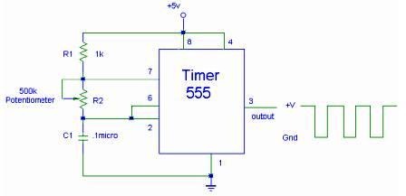
The setup for the Square Wave Generator can be initiated using a 555 timer IC as illustrated in the accompanying circuit diagram. It is essential to reference the pinout configuration of the 555 timer IC. An oscilloscope should be...
The technical parameters of high-speed optocouplers include a rise time (t1) of less than or equal to 300 ns, a circuit transfer ratio (CTR) of 50%, an isolation voltage (VSO) of at least 15,000 V, and an output transistor...

Power demand in portable designs can require, in specific applications, more than 1 A. A method involves paralleling two DC to DC converters on the same load instead of using a single higher current converter with a lower switching...