
Automatic light regulator circuit diagram

This automatic brightness control circuit utilizes a thyristor (VT1) in conjunction with a series of diodes (VD1 to VD4) to implement a full-wave phase control mechanism. The function of the diodes is to rectify the AC input, allowing for a controlled output that varies based on the ambient light levels detected by the circuit. The neon tube (N) acts as a triggering device for the thyristor, ensuring that the thyristor only conducts when the ambient light falls below a certain threshold.
The core operation of the circuit hinges on the adjustment of the capacitor (C), which influences the charging time constant. By altering this time constant, the conduction angle of the thyristor can be modified, thereby affecting the average power delivered to the load (lights). In bright conditions, the capacitor charges quickly, resulting in a smaller conduction angle and consequently lower light output. Conversely, in darker conditions, the capacitor charges more slowly, increasing the conduction angle and allowing more power to flow to the lights, thus enhancing their brightness.
The design of this circuit is particularly effective for applications where ambient light levels fluctuate, such as outdoor lighting or streetlights, providing an energy-efficient solution that adapts to changing conditions. The use of a thyristor not only facilitates effective control of the lighting but also contributes to the durability and reliability of the circuit, making it suitable for various electronic applications. As shown, this circuit can automatically adjust the brightness according to ambient light intensity of light. If outside, high brightness, light on dark, whereas low ambient br ightness, lights come on. FIG thyristor VT1 and diode VD1 ~ VD4 circuit composed of a full-wave phase control, with neon tube N for VT1 trigger tube. W can be adjusted to change the capacitor C charging time constant, that change VT1 conduction angle control the brightness of light.
Related Circuits
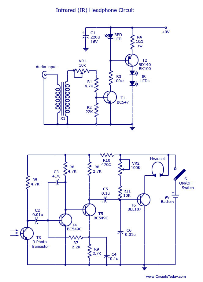
This document outlines a simple infrared (IR) headphone circuit designed for listening to television or radio without disturbing others. The IR headset is a preferable option for beginners compared to FM headsets due to its desirable sound quality that...
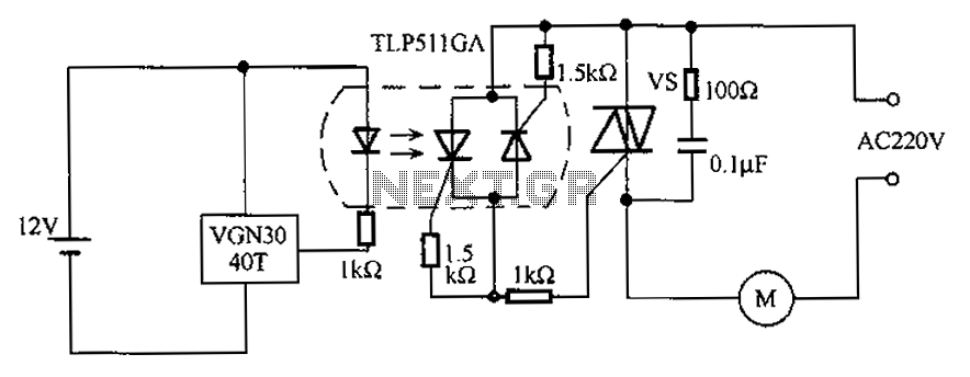
The circuit utilizes an integrated Hall effect sensor for an AC motor control system. It operates by detecting the presence of magnets or other magnetic objects near the Hall IC element of the induction motor. This configuration functions as...
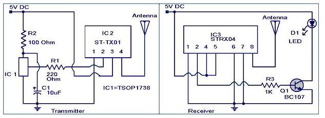
The IR to RF transmitter circuit described here can convert infrared (IR) signals from a remote control into radio frequency (RF) signals, allowing for long-distance transmission. This circuit effectively extends the range of an IR remote control and does...
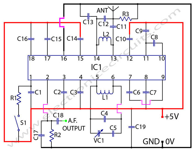
TDA7000 FM Radio Receiver Circuit Using Tuning Capacitor GENERAL DESCRIPTION The TDA7000 is a monolithic integrated circuit for mono FM. The TDA7000 is designed as a complete FM radio receiver circuit, integrating all necessary functions for receiving mono FM signals....
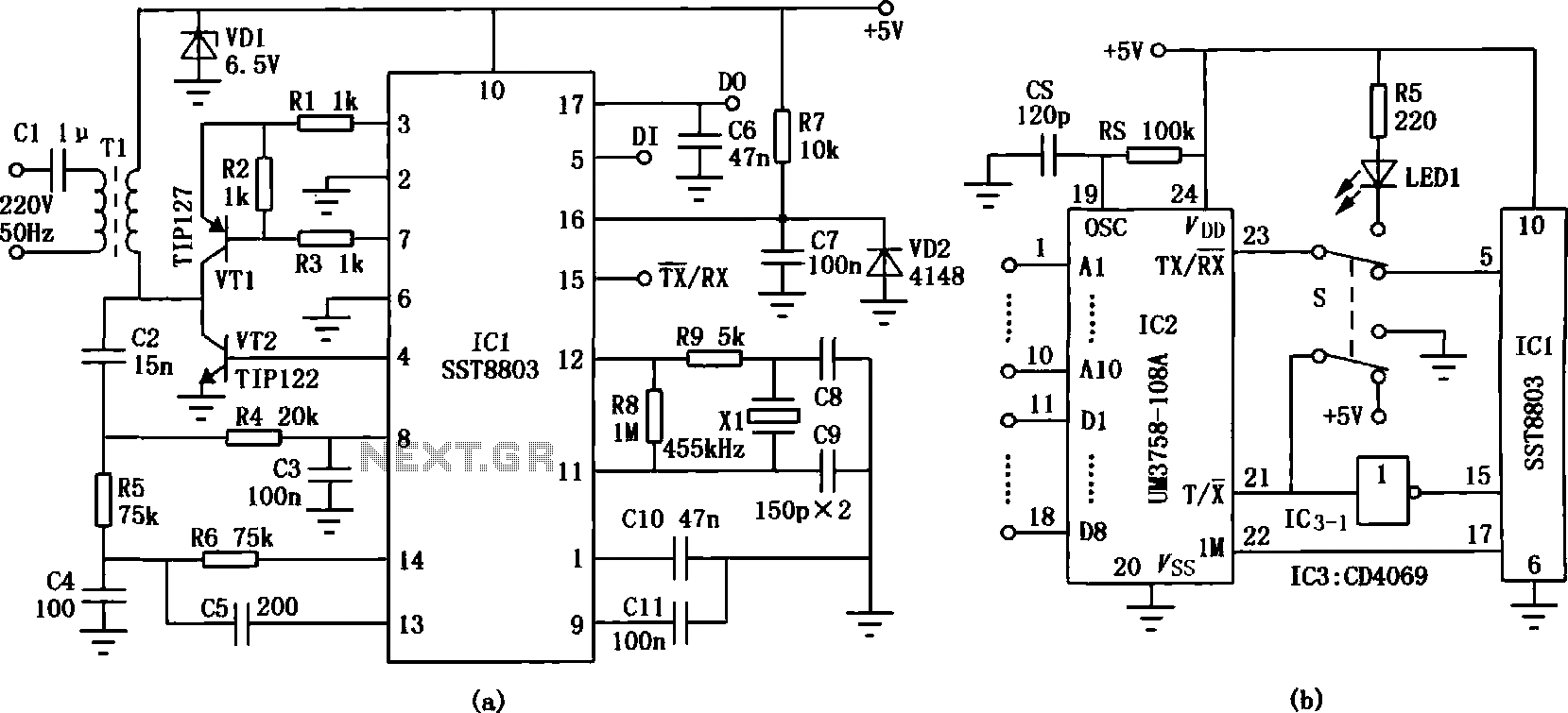
The transmission circuit for inductive wireless headsets must be securely mounted on a wall or ceiling, limiting its outdoor usability, which is a significant disadvantage of inductive wireless headphones. In contrast, infrared wireless headsets utilize a compact infrared transmitter...
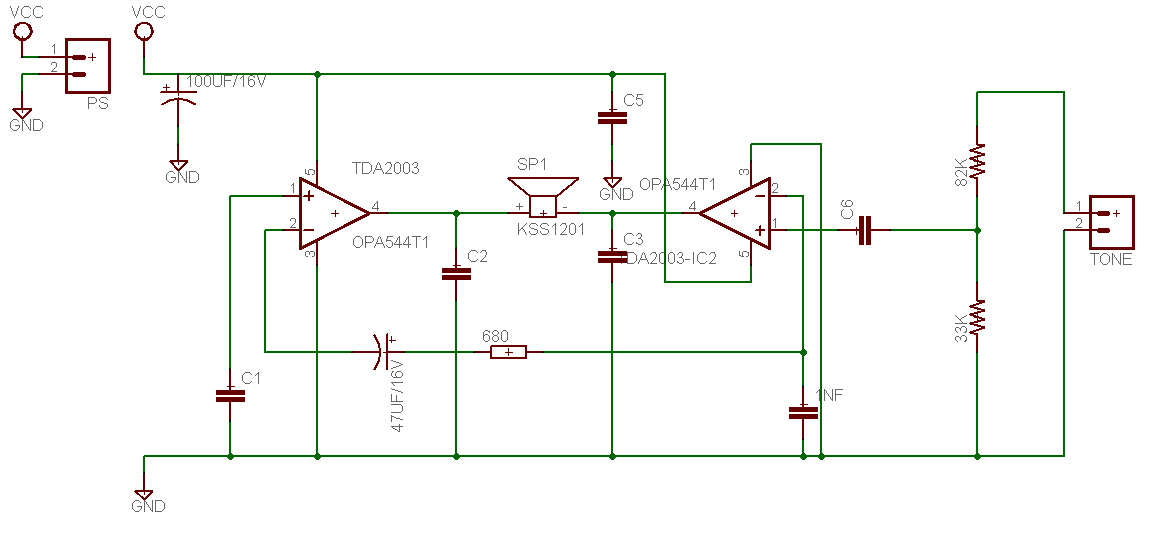
This is a design for a tone control circuit. The circuit features the LM1036, which is a DC-controlled tone (bass/treble), volume, and balance circuit suitable for stereo applications in car radios, televisions, and audio systems. The LM1036 integrated circuit is...