
TDA7000 FM Radio Receiver Circuit
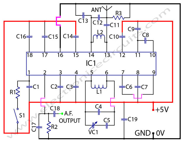
The TDA7000 is designed as a complete FM radio receiver circuit, integrating all necessary functions for receiving mono FM signals. It utilizes a tuning capacitor to adjust the frequency, allowing the user to select different radio stations. This integrated circuit is particularly noted for its simplicity and efficiency, making it suitable for various applications in consumer electronics.
The circuit typically includes an antenna input, a frequency-selective circuit, a demodulator, and an audio output stage. The tuning capacitor is crucial for enabling the selection of the desired frequency by varying the capacitance, which subsequently alters the resonant frequency of the circuit. This process allows the circuit to lock onto the frequency of the incoming FM signal.
In terms of operation, the TDA7000 requires a power supply, often in the range of 3 to 9 volts, which powers the internal components. The circuit can be configured with external components such as resistors and capacitors to optimize performance based on specific requirements. The output of the TDA7000 can be connected to an audio amplifier or directly to a speaker, providing a straightforward audio output for the user.
The design of the TDA7000 circuit emphasizes minimal external components, which not only simplifies the assembly but also reduces the overall cost of the FM receiver system. This makes it an ideal choice for hobbyists and engineers looking to implement FM radio functionality in their projects without extensive design complexities.TDA7000 FM Radio Receiver Circuit Using Tuning Capacitor GENERAL DESCRIPTION The TDA7000 is a monolithic integrated circuit for mono FM.. 🔗 External reference
Related Circuits
This sound effects circuit is designed to function as a signal distorter. When utilized with an electric guitar, it enables the creation of unique sound effects. The sound effects circuit operates by manipulating the input audio signal from the electric...
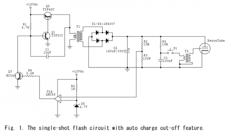
A voltage divider is created using resistors R2 (10MΩ) and R3 (100KΩ), which effectively reduces the voltage across capacitor C2 by a factor of approximately 100. The ground of C2 is connected to the inverter ground for reference. An...
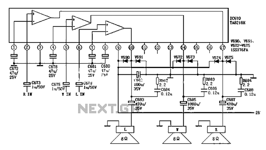
The audio circuit depicted in the figure is commonly utilized in color television systems. The pin functions and reference voltages for the TA8218AH are as follows: Pin 1: 1.9V - inverting input; Pin 2: 2.1V - R-channel audio signal...
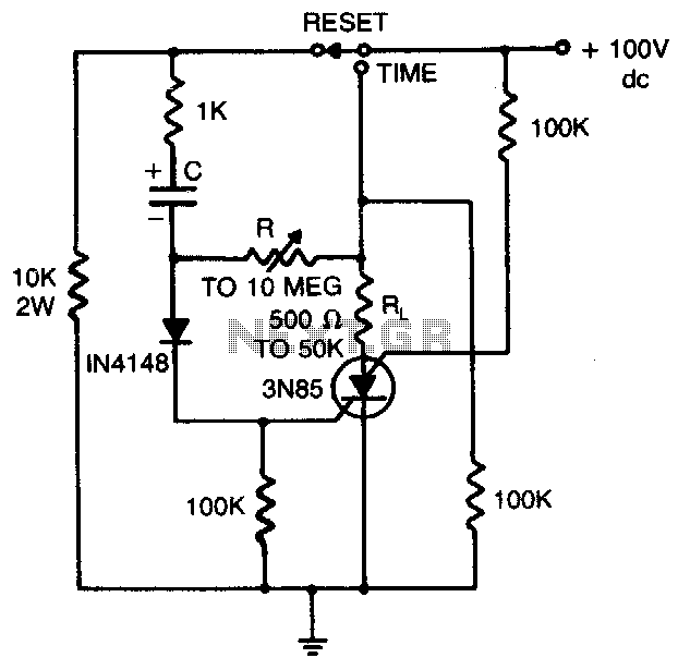
Load current starts approximately 0 RC after the switch is thrown. The statement indicates that the load current begins at approximately 0 ohms after a switch is activated. This scenario is common in electronic circuits where a switch controls the...

In this circuit, U1 is a frequency converter that supplies the 455-kHz intermediate frequency (IF) stage U2 and detector U3. U4 serves as the audio output stage. R9 functions as a gain control, allowing for the adjustment of the...
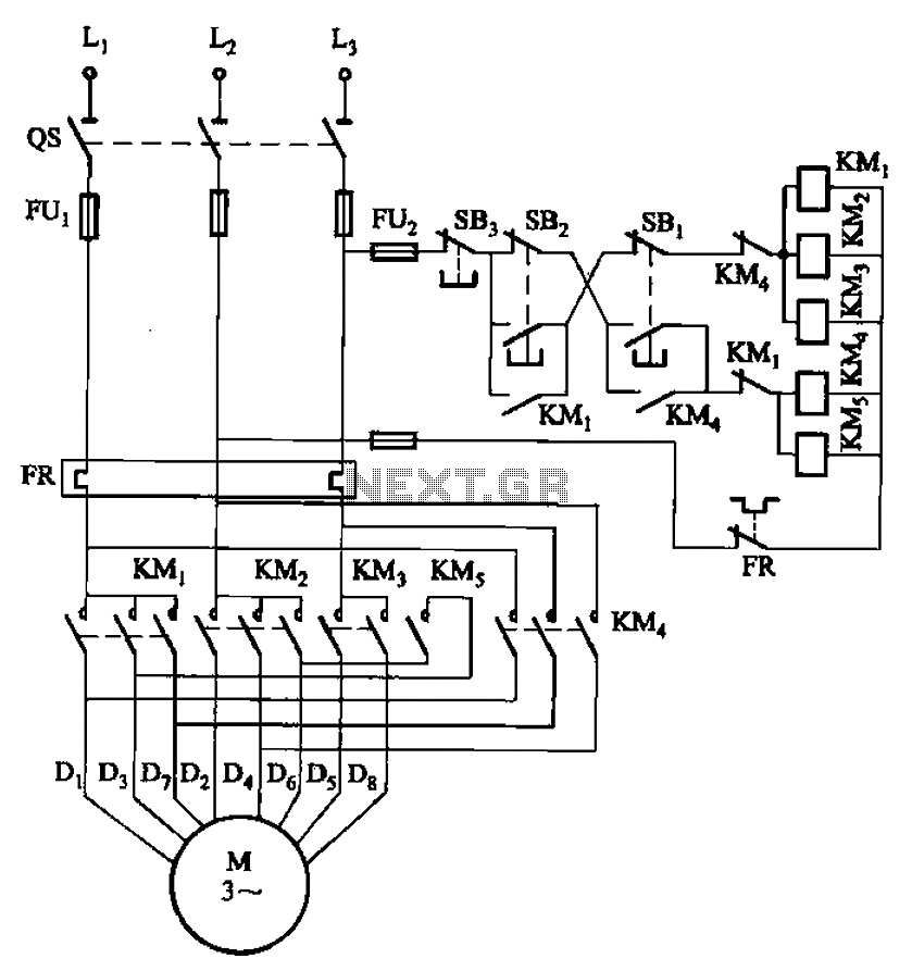
The circuit illustrated in Figure 3-104 features SB2, which functions as the low-speed operation button, and SBi, which serves as the high-speed operation button. The circuit design utilizes two distinct operational buttons, SB2 and SBi, to control the speed of...