
automatic night lamp 230v

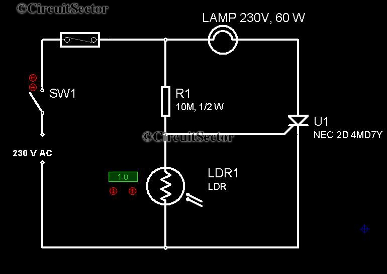
The automatic night lamp circuit operates on the principle of light detection and control using fundamental electronic components. The core of the circuit is the LDR, which changes its resistance based on ambient light levels. In bright conditions, the LDR maintains low resistance, preventing the SCR from turning on. As darkness falls, the resistance of the LDR increases, triggering the SCR to conduct. This action allows the AC voltage to flow to the lamp, illuminating it automatically.
The SCR is a crucial component in this design, functioning as a switch that can handle high voltage and current. It remains off until triggered by the LDR, ensuring that the lamp only activates under the desired conditions. The 4.7M variable resistor provides an adjustable sensitivity setting, allowing the user to fine-tune the light threshold at which the lamp activates. This feature is particularly useful in varying environmental conditions, such as different times of the year or locations with differing ambient light levels.
When designing this circuit, it is essential to ensure proper insulation and safety measures, especially since it operates at 230V AC. Use components rated for the required voltage and current, and ensure that all connections are secure to prevent short circuits or accidental contact with live parts. A suitable enclosure should be used to house the circuit, providing additional safety and protecting the components from environmental factors.
Overall, this automatic night lamp circuit exemplifies a simple yet effective application of basic electronic principles, providing convenience and energy savings by only activating when needed.Here is a project of a simple automatic night lamp circuit or dark activated 230V lamp circuit, which will automatically activate an AC lamp / bulb when sun set or if the circuit will receive no light. The circuit is very easy to build using no more than five components. The LDR is working as a light/dark sensor and SCR is working as a switch. Whe n light falls on the LDR its resistance will decrease and the SCR will remain in the off condition but when the LDR will receive no light its resistance increases which will switch on the SCR and 230V AC voltage will start passing through the SCR which will power on the 230V lamp. The sensitivity of the circuit can be adjusted with 4. 7M variable resistor. Note: Many of its points are at AC mains voltage. It could give you lethal shock if you are not careful. If you don`t know much about working with AC line voltages do not attempt to construct this circuit. 🔗 External reference
Related Circuits
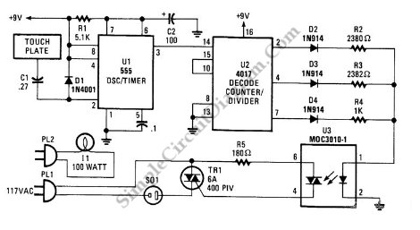
This is a three-mode lamp dimmer circuit with touch control. This circuit can be used to control a lamp in three operation modes: dim, off, and bright. A NE555 timer is utilized in the design. The three-mode lamp dimmer circuit...
The automatic sprinkler controller circuit consists of a power supply circuit and a humidity measurement and control circuit, as illustrated in the accompanying figure. The power supply circuit includes a power transformer (T), rectifier diodes (VD1 to VD4), filter...
For several years, a rear fog lamp has been mandatory for trailers and caravans to enhance visibility in foggy conditions. When the fog lamp is activated, the fog lamp of the towing vehicle must be turned off to prevent...
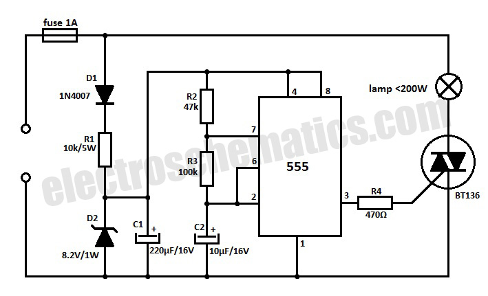
This 220V mains operated solid-state flashing lamp circuit utilizes a 555 timer integrated circuit (IC) to manage the ON and OFF durations of a triac that regulates power to the load. The circuit operates at a mains voltage of 220V,...
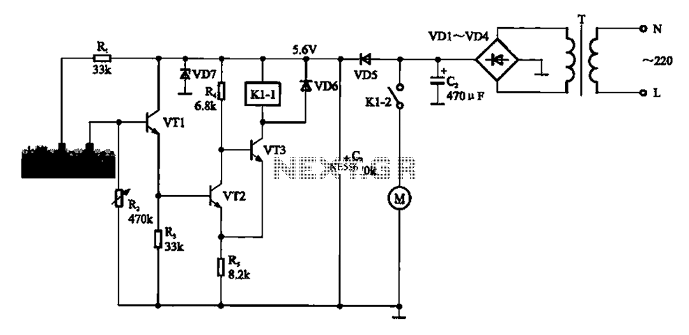
Automatic sprinkler control circuit. This circuit primarily consists of a humidity sensor, a detection signal amplifying circuit (including transistors VT1, VT2, and VT3), a power supply circuit (comprising a filter capacitor C2, a bridge conditioning circuit UR, and a...
It is very convenient to automatically light a lamp in our absence during the evening when it gets dark. This automatic night lamp circuit can be utilized to illuminate staircase lights, porch lights, etc., automatically using a domestic power...