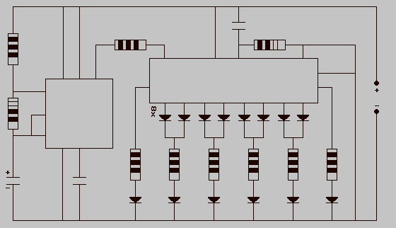
Fully Automatic Emergency Light

This simple automatic emergency light has advantages over conventional emergency lights: the charging circuit stops automatically when the battery is fully charged.
This automatic emergency light features a straightforward design that enhances its operational efficiency compared to traditional emergency lighting systems. The primary advantage lies in its automatic charging circuit, which ceases operation once the battery reaches full charge. This functionality serves to prevent overcharging, thereby extending the lifespan of the battery and ensuring reliable performance when needed.
The circuit typically consists of a power supply unit, a rechargeable battery, a charging controller, and LED light sources. The power supply unit converts the mains voltage to a suitable level for charging the battery. The battery, often a sealed lead-acid or lithium-ion type, stores energy for use during power outages.
The charging controller is crucial in managing the charging process. It monitors the battery voltage and current, automatically disconnecting the charging circuit when the battery is fully charged. This feature not only protects the battery but also enhances safety by reducing the risk of overheating or leakage.
LED light sources are commonly used in these emergency lights due to their low power consumption and high brightness. They provide efficient illumination during an emergency, ensuring visibility in dark conditions.
Overall, this automatic emergency light system is designed to provide reliable, maintenance-free operation, making it a valuable addition to safety equipment in residential, commercial, and industrial settings.This simple automatic emergency light has the following advantages over conventional emergency lights: The charging circuit stops automatically when the b.. 🔗 External reference


