
Automatic sprinkler controller circuit diagram 3

The automatic sprinkler controller circuit is designed to manage irrigation systems efficiently by automating the watering process based on environmental conditions. The circuit's power supply section, operating at +12 V, is crucial for providing the necessary voltage to the entire system.
The knife switch (Q) serves as a manual disconnect, allowing maintenance or troubleshooting without powering the entire circuit. The fuse (FU2) acts as a protective element, ensuring that the circuit is safeguarded against overcurrent conditions, which could potentially damage the components.
The power switch (S1) allows for easy activation and deactivation of the circuit, facilitating user control over the irrigation system. The power transformer (T) steps down the voltage from the mains to a suitable level for the circuit, while the rectifier diodes (VD1 to VD4) convert the alternating current (AC) output from the transformer into direct current (DC), which is necessary for the operation of the subsequent components.
The filter capacitors (C1 and C2) stabilize the DC output by smoothing out any voltage fluctuations, providing a steady voltage supply to the light control and irrigation control circuits. The light control circuit is likely responsible for monitoring ambient light levels, enabling the system to operate only during specific times of the day, thereby conserving water and energy.
The irrigation control circuit activates the sprinkler system based on the signals received from the light control circuit or other environmental sensors, ensuring that plants receive the appropriate amount of water. This automated approach not only enhances the efficiency of water usage but also promotes healthier plant growth by providing optimal watering conditions.
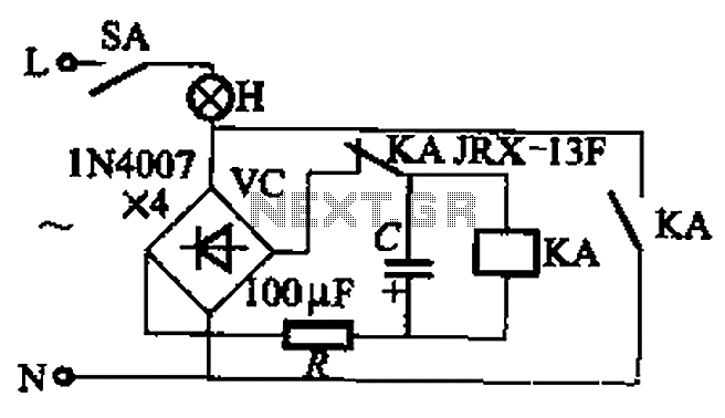
Overall, the integration of these components within the automatic sprinkler controller circuit exemplifies a well-designed system aimed at improving agricultural practices through automation.The automatic sprinkler controller circuit is composed of the +12 V power supply circuit, light control circuit and irrigation control circuit, and the circuit is shown as the Figure. +12 V power supply circuit is composed of the knife switch Q, fuse FU2, power switch S1, power transformer T, rectifier diodes VD1 ~ VD4, filter capacitors C1, C2, and three-te..
🔗 External reference
Related Circuits
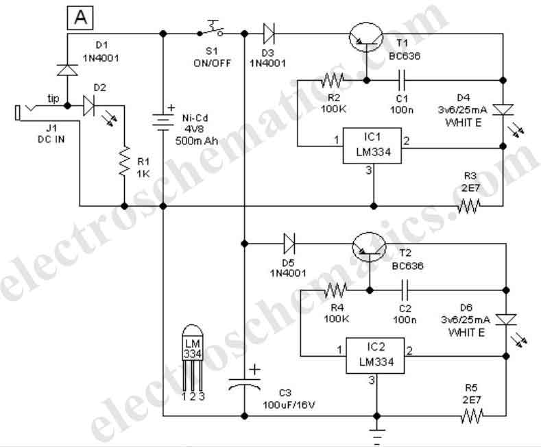
This easy-to-construct handy pen torch electronic circuit has a low component count and utilizes two power white LEDs for illumination. A low voltage (4.8V DC) supply is derived from a built-in rechargeable Ni-Cd battery pack and is converted into...
This circuit is designed for children's entertainment and can be installed on bicycles, battery-powered cars, motorcycles, as well as on models and various games and toys. When switch SW1 is positioned as depicted in the circuit diagram, it generates...
This project measures the clock pulses supplied to the Timer input of the AVR microcontroller. The Bascom code counts the clock pulses over a duration of 1 second and displays the result. The circuit for this project primarily consists of...
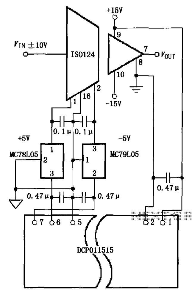
The circuit depicted in the figure includes the ISO124 and MC78L05 components, along with an external regulator, MC79L05, and the DCP011515, which collectively enhance the power supply rejection ratio (PSR) of the circuit. The input signal, VIN (maximum swing...
As a cyclist, there is a constant search for methods to enhance visibility during nighttime rides. The concept of the `NITE-RIDER` was developed to create a distinctive and attention-grabbing rear light for bicycles. This design features nine extra-bright LEDs...
The circuit illustrated in Figure 13-3 consists of two configurations: (a) a DC power supply and (b) an AC power supply. Both configurations are utilized to control a relay. The flash frequency of the relay is determined by the...