
Automatic Turn-Off Alarm With Delay

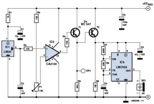
The circuit utilizes two operational amplifiers configured as a monostable multivibrator, where IC1A acts as the trigger input and IC1B serves as the output control. The sensors, designated as SI to S5, are connected to the input of IC1A, which monitors the sensor signals. Upon receiving a valid trigger signal from any of these sensors, IC1A transitions to a logic low state.
This transition causes IC1B to activate transistor Q1, allowing current to flow through the load connected to Q1. The output remains active until capacitor C3, which is charged during the operation, discharges through resistor R6. The time constant for this discharge is determined by the values of C3 and R6, which effectively sets the duration of the output signal from IC1B.
As C3 discharges, the voltage across it decreases, eventually reaching a threshold that resets both IC1A and IC1B. This reset action brings the circuit back to its initial state, ready to respond to the next trigger from the sensors. The design ensures that the output pulse duration can be adjusted by varying the capacitance of C3 or the resistance of R6, providing flexibility in timing applications. The overall functionality is critical in applications requiring precise timing and control based on sensor inputs. In this circuit, IC1A and IC1B act as a monostable multivibrator. Any input from the sensors SI through S5 forces IC1A to produce logic low, which causes IC1B to turn on Ql until C3 changes through R6. This action resets the latch formed by IC1A and IC1B.
Related Circuits
This low voltage circuit can be used to monitor batteries and other volatile sources of current for problems. The circuit sounds an alarm and lights an LED, but can be interfaced to any number of other circuits for many...
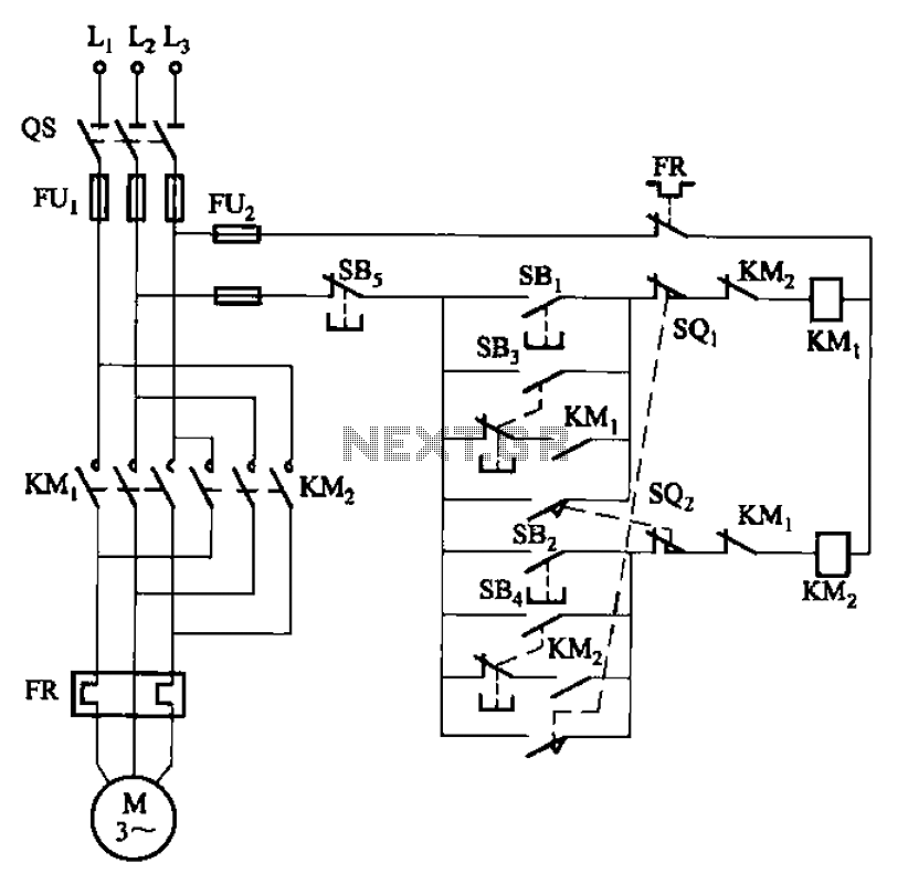
The circuit depicted in Figure 3-27 features a jog function that allows for precise adjustments of moving components. In the figure, SB3 and SB4 represent the forward jog and reverse jog buttons, respectively. When the SB3 button is pressed,...

An efficient automatic solar garden lights circuit with minimal components. The notable feature is that it operates entirely automatically, with the solar panel functioning as a light detector. The automatic solar garden lights circuit is designed to provide illumination in...
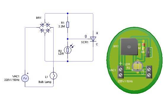
Adjust the value of R1 to achieve optimal performance of the LDR sensor. If, in practice, a resistance of 2.2 MΩ still activates the lamp, it is possible to increase the value of R1 to a larger resistance of...
The overhead detector (fire alarm) circuit utilizes a precision integrated temperature sensor, the LM35 (IC1), which offers an accurate linear output. The overhead detector circuit is designed to monitor ambient temperature levels for fire detection purposes. The core component of...
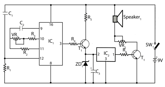
The circuit timer with a musical alarm utilizes a well-known CMOS oscillator/divider integrated circuit (IC1). Although this circuit operates at 9V, its standby current drain is minimal. The time delay of the timer circuit can be adjusted by modifying...