
Why are 555 IC pin diagrams so random

The 555 timer IC is a versatile device widely used in various electronic applications, including timing, pulse generation, and oscillation. It generally comes in an 8-pin dual in-line package (DIP) format, where the pin configuration is standardized across most manufacturers. The standard pinout includes pins for power supply, ground, trigger, threshold, discharge, control voltage, reset, and output.
Despite the standardization, variations can exist between manufacturers, particularly in the electrical characteristics and maximum ratings of the components. It is essential to refer to the specific datasheet of the manufacturer to confirm the exact pin configuration and electrical specifications, as this can impact the circuit's performance.
When designing circuits with the 555 timer, it is advisable to maintain a clear and consistent schematic that reflects the actual pin configuration used in the circuit. If custom routing is necessary to accommodate different pin arrangements, it is crucial to document these changes meticulously to avoid confusion during assembly or troubleshooting. Additionally, using a breadboard for prototyping can help visualize the connections before finalizing the PCB layout, ensuring that the intended functionality is achieved without ambiguity.
In summary, while the 555 timer chips are largely interchangeable, attention must be paid to the specific pin configurations and characteristics of the selected component to ensure proper functionality in any given application.Can I assume that most of the 555 chips from different manufacturers are interchangable (same pin configuration), however the programs/diagrams have pins that way just to look simpler I can always route my own weird ways on the actual chip to match the configuration in the schematics, however that is confusing due to it changing each time. 🔗 External reference
Related Circuits

The circuit below demonstrates the generation of a single positive pulse that is delayed in relation to the trigger input time. It is similar to a previously described circuit but utilizes two stages, allowing for control over both the...
It was observed that balls were becoming lodged in the ball trough, failing to load into an upkicker or not resting correctly on the trough ball microswitches or optos, which caused the machine to register a missing ball. Initially,...
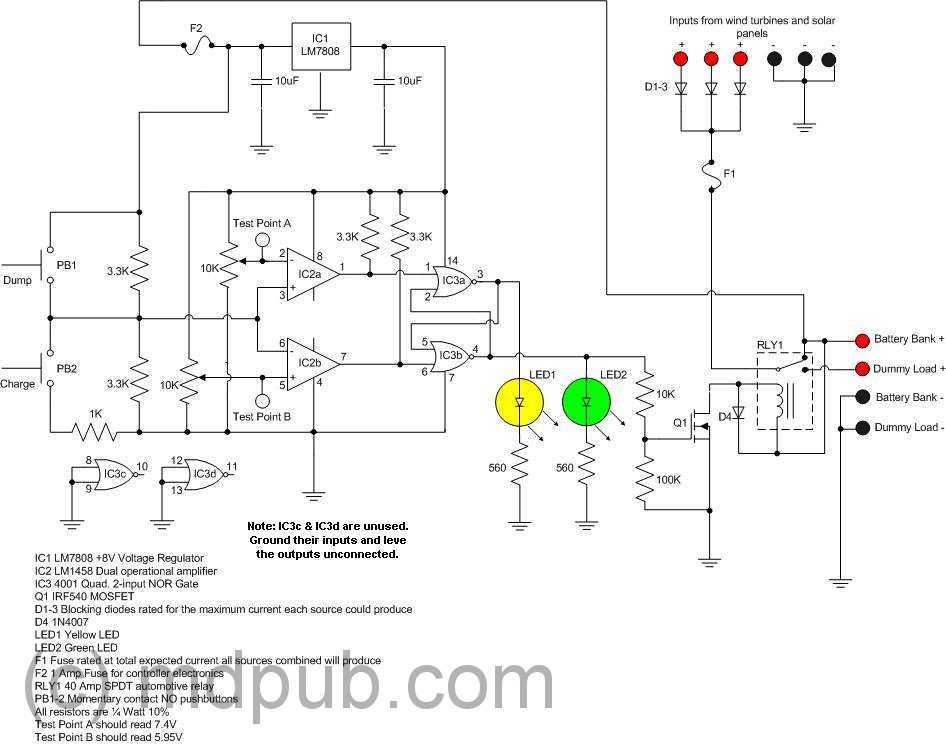
The prototype was successfully assembled on a breadboard and subsequently built on a piece of Radio Shack protoboard for field use. The assembly process took only a couple of hours, and it functioned correctly on the first attempt. This...
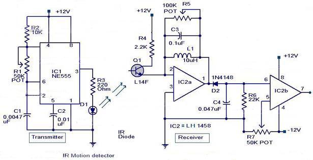
The following circuit illustrates an Infrared Motion Sensor circuit diagram. Features include the use of the NE555 integrated circuit, with a detection zone coverage of 80 degrees. The Infrared Motion Sensor circuit utilizes the NE555 timer IC configured in a...
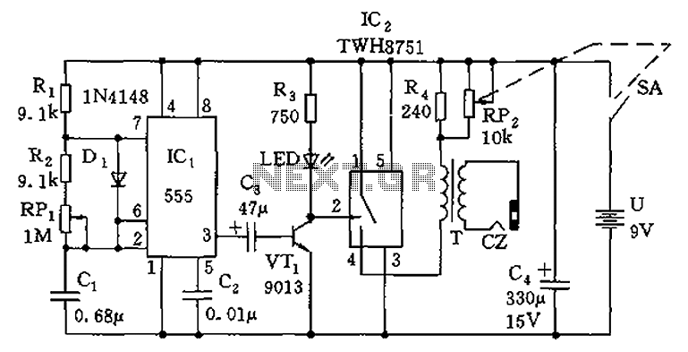
The circuit is composed of a 555 oscillator and an amplifier driver stage. It includes the 555 timer along with resistors R1, R2, RP1, capacitor C1, and other components forming a multi-harmonic oscillator. The frequency can be adjusted using...
Electronics tutorial about the 555 oscillator and how the 555 oscillator can be used as a 555 astable oscillator circuit to generate square wave waveforms. The 555 timer IC is a versatile and widely used component in electronics, particularly for...