
Automatic water tank circuit diagram

The automatic water tank system utilizes a PSSR AC solid-state relay to control the filling and draining of water in the tank. The PSSR is chosen for its robust performance in AC applications, providing enhanced functionality compared to conventional SSRs. This relay operates by switching the AC load on and off based on the water level detected by sensors installed in the tank.
In this system, water level sensors are strategically placed at various heights within the tank. These sensors continuously monitor the water level and send signals to the PSSR relay. When the water level falls below a predefined threshold, the sensor activates the relay, which in turn powers the water pump to fill the tank. Conversely, when the water level reaches a certain upper limit, the sensor deactivates the relay, stopping the pump to prevent overflow.
The advantages of using a PSSR relay in this application include its low noise operation, which is essential in residential settings, and its reliable performance, minimizing the risk of system failures. Additionally, the passive load power drive feature allows the relay to manage various load types efficiently, ensuring that the water pump operates optimally under different conditions.
Overall, this automatic water tank system exemplifies modern advancements in solid-state relay technology, providing an efficient and reliable solution for water management in various applications. The integration of sensors and a PSSR relay enhances the system's automation capabilities, promoting water conservation and operational efficiency. Automatic water tank as shown in the circuit diagram. IC is PSSR AC solid state relay, which is developed in the SSR on the basis of a new type of solid-state relays AC non-con tact relay, compared with the SSR, it not only has an active SSR drive function, but also has the drive and passive load power drive function. Simple PSSR solid state relay has a structure, reliable operation, low noise advantages.
Related Circuits
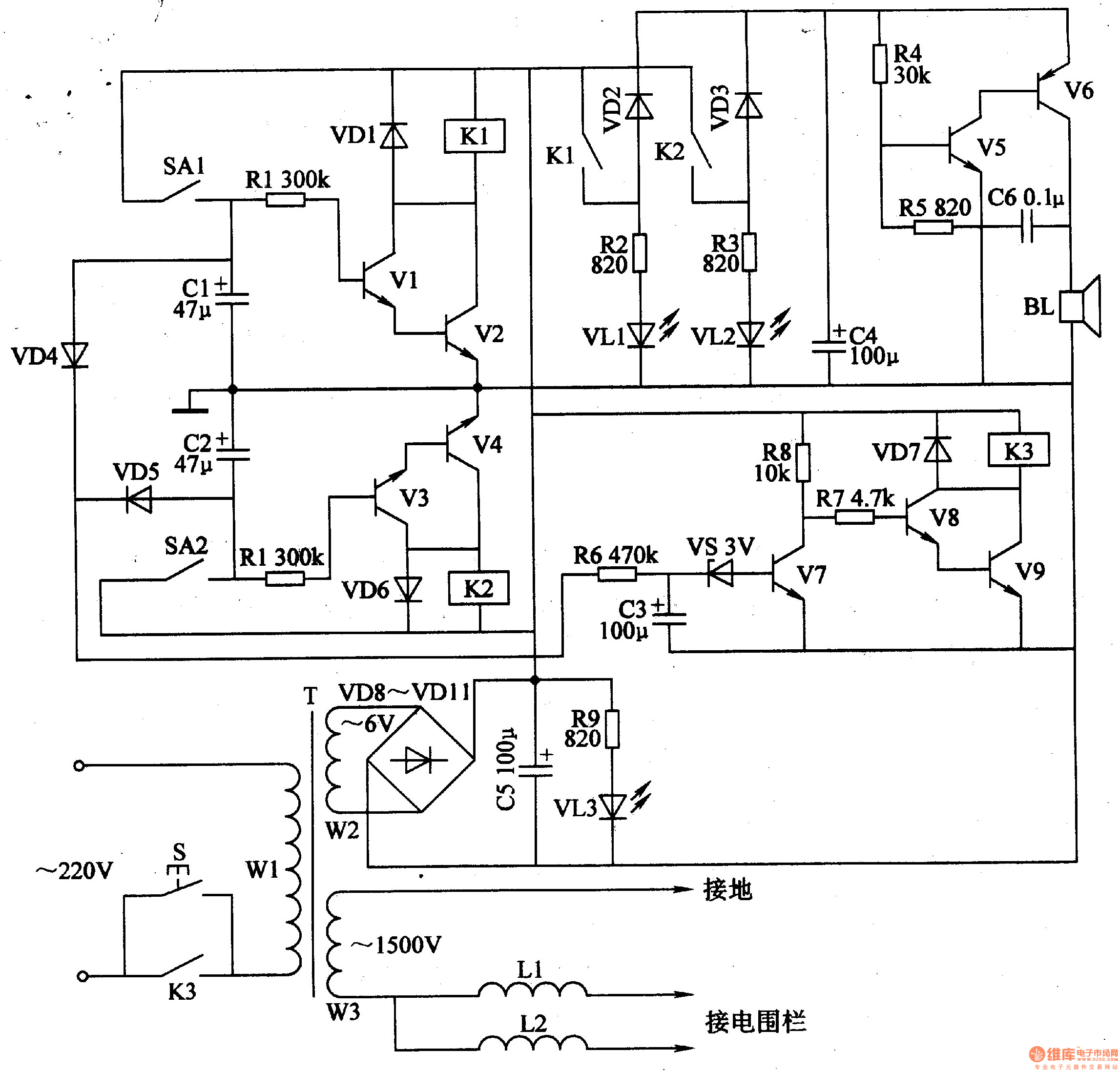
The electric fence control circuit includes a +6 V power supply circuit, a high-voltage output circuit, a trigger control circuit, an alarm circuit, and a protection circuit. The +6 V power supply circuit consists of a power control button...
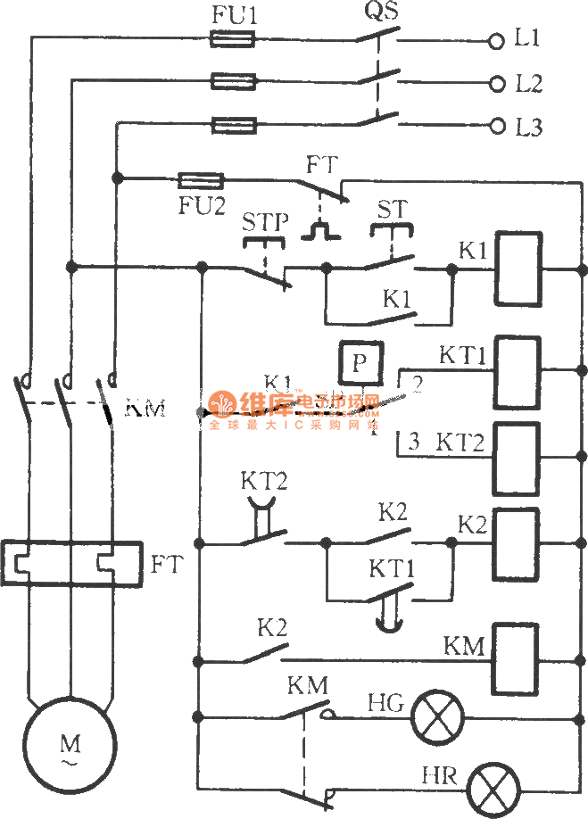
The circuit utilizes two time relays, KT1 and KT2, which are connected in series with the contacts of an electric contact pressure gauge (SP). This configuration helps to mitigate issues such as tremors or sparking that may occur due...

The simple pulse width modulation circuit is illustrated in the figure. It utilizes an operational amplifier to create a multivibrator, resulting in a symmetrical oscillation output signal with a duty cycle of 50%. By adjusting the external threshold voltage,...
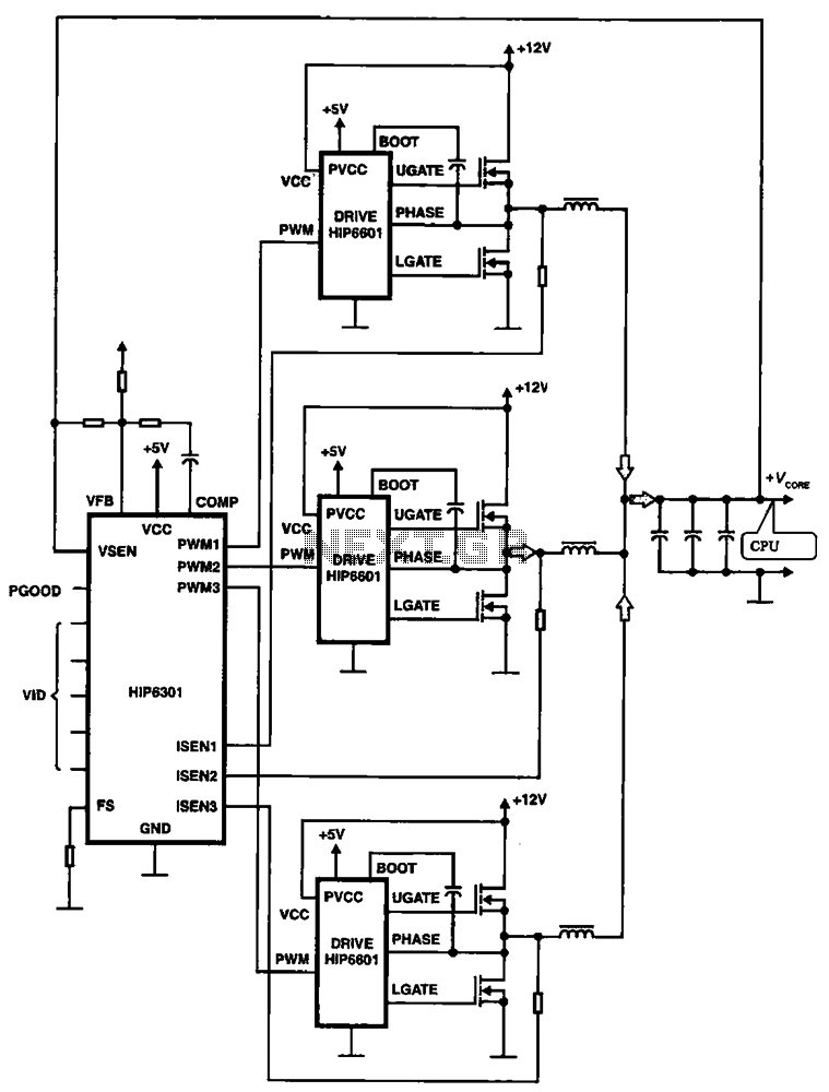
HIP6301 and HIP6601 are used in a 3-phase CPU power circuit. The HIP6301 and HIP6601 are integrated circuits designed for power management in CPU applications, particularly in multi-phase power supply systems. The HIP6301 is a high-performance synchronous buck controller,...
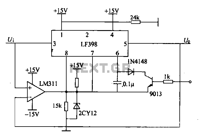
The peak voltage sample and hold circuit is illustrated in Figure 12-50. This circuit comprises the LF398 sample and hold chip and the LM311 voltage comparator. The LF398 is responsible for outputting and inputting voltages. The LM311 compares the...
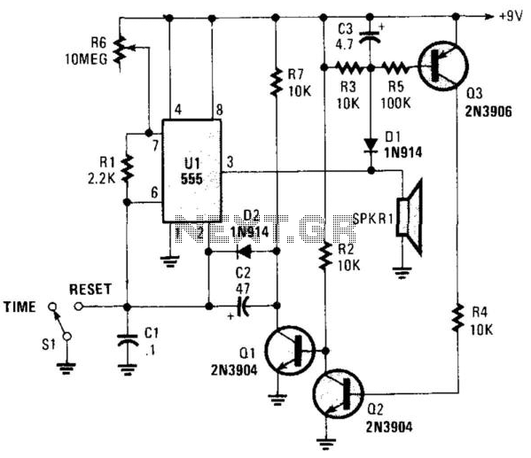
This circuit operates in astable mode and produces a tone at the end of the first period, which can last several minutes. When switch SI is in the time position, transistor Q3 is turned off because pin 3 of...