
Three ECC83-Based Tube Phono Preamplifier Circuits

The described circuits utilize the ECC83 vacuum tube, a dual-triode component known for its low noise and high gain characteristics, making it suitable for high-fidelity audio applications. Each circuit is configured as a phono preamplifier, which is essential for amplifying the low-level signals generated by vinyl records to a standard line level suitable for further processing or amplification.
The adherence to RIAA (Recording Industry Association of America) standards ensures that the frequency response of the phono preamplifiers is optimized for vinyl playback. This involves applying a specific equalization curve that compensates for the inherent frequency response of vinyl records, which is crucial for accurate sound reproduction.
The circuit design may include a power supply section, providing the necessary high voltage for the ECC83 tubes, typically around 250V. Additionally, the signal path may feature coupling capacitors to block DC components while allowing AC signals to pass, ensuring that the audio signal remains intact.
Feedback mechanisms could be integrated to enhance linearity and reduce distortion, which is particularly important in audio applications where clarity and fidelity are paramount. The output stage may be designed to drive standard audio equipment inputs, ensuring compatibility with various amplifiers and sound systems.
Overall, the design of these phono preamplifiers emphasizes high-quality audio performance, low distortion, and compliance with industry standards, making them suitable for audiophiles and professionals in the recording industry.The three circuits were based on the vacuum tube ECC83 designed to produce phono preamplifiers in compliance with the RIAA standards. Recording Industry A.. 🔗 External reference
Related Circuits
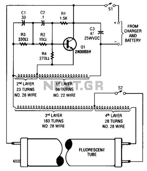
A 2N3055 oscillator (Q1) drives a homemade transformer, wound on a Vk ferrite rod. S2 is used as a filament switch and can be eliminated if desired. A 20-W fluorescent tube is recommended. The supply voltage is 12 V. The...
This circuit enables the brake light to flash. The default behavior occurs when power is supplied to the circuit or when the brake is engaged. The timer IC (IC2) drives current to the transistor (Q2), producing an oscillating output...
The circuit was submitted by an individual from Newtownabbey, Northern Ireland. It has an exceptionally fast high frequency response, as demonstrated by applying a 100kHz squarewave to the input. All graphs were produced using Tina Pro. The circuit in question...
If the audio input is a microphone, it is expected to precede an amplifier to achieve an output power of approximately 8W. The amateur seeking to enhance a small transmitter, which is likely already constructed, can utilize this circuit,...
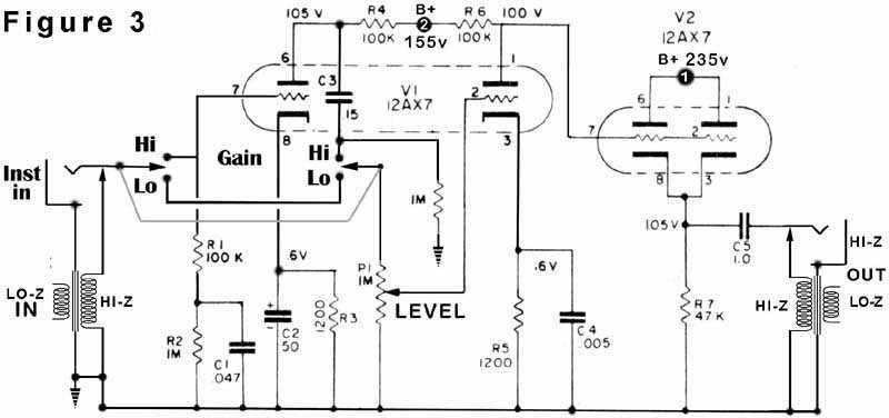
Figure 1 shows distortion variations in red and violet. Notice how the violet wave follows the green wave perfectly during its positive excursion but falls short of the mark during the negative swing. The red wave is more symmetrical,...
This circuit utilizes a single 555 Timer IC and a small transformer to generate high voltage for testing zener diodes with voltage ratings up to 50VDC. The 555 timer operates in astable mode, with the output at pin 3...