
Precision Dark-Activated Switch With Hysteresis Circuit

The described circuit utilizes a GdS (Gallium Sulfide) light sensor, which is sensitive to changes in light levels. In this configuration, the GdS cell is integrated into a bridge circuit, which typically consists of four resistive elements arranged in a diamond shape. The bridge circuit is designed to measure the imbalance created by changes in light intensity, which affects the resistance of the GdS cell. This imbalance generates a voltage difference across the bridge, which can be monitored.
Potentiometer R6, positioned in one leg of the bridge, is used to set a specific trip point. This trip point determines the threshold at which the circuit responds to changes in light intensity. By adjusting R6, the user can define the sensitivity of the circuit, allowing it to activate or deactivate based on the desired light level.
Potentiometer R5 is incorporated into the circuit to provide hysteresis. Hysteresis is a critical feature that helps stabilize the operation of the relay by preventing rapid on-off cycling, often referred to as chattering or hunting. This is achieved by introducing a delay in the turn-off point of the circuit, ensuring that the light level must increase significantly beyond the trip point before the transistor 2N3904 turns off. This design consideration is crucial in applications where stable operation is necessary, such as in lighting control systems or automatic light sensors.
The 2N3904 transistor functions as a switching element in this circuit. When the light level falls below the defined trip point, the transistor is activated, allowing current to flow through the relay, which in turn can control larger loads. Conversely, when the light level rises sufficiently, the transistor turns off, deactivating the relay and stopping the current flow. This behavior ensures that the circuit responds effectively to changes in ambient light conditions while maintaining reliable operation. A GdS cell is one leg of a bridge circuit. Potentiometer R6 iri another leg sets the trip point. Potentiometer R5 provides hysteresis adjustment to prevent chattering or hunting of the relay. The light level has to increase noticeably before the 2N3904 turns off and the circuit deactivates.
Related Circuits

A schematic of a typical transistor AM radio is presented. This circuit utilizes npn transistors. It is a generic circuit; hence, specific values for some components are not provided. This circuit serves as a reference point for experimenters. The schematic...
This circuit-based project demonstrates the operation of a 555 timer in astable mode to generate pulses with a time period of 0.5 seconds. These pulses can be utilized in various applications, such as blinking an LED or creating decorative...
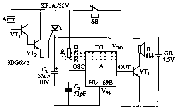
The circuit utilizes the HL-169B voice alarm integrated circuit (IC). It is designed for use in security applications, including glass doors, car doors, and windows, to act as a burglar alarm. When a thief applies force to these items,...

It utilizes the SHD series of electronic control equipment modules. The fan control box KZH functions as the HKD 1F electronic module. The SHD series of electronic control equipment is designed for various applications, including fan control systems. Within this...

This is the design circuit diagram of an ultrasonic mosquito repeller. The circuit operates based on the theory that insects, such as mosquitoes, can be repelled by sound frequencies in the ultrasonic range (above 20 kHz). The circuit utilizes...
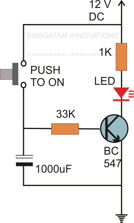
Without the specified delay, the circuit could malfunction or even sustain damage. A capacitor, which is a crucial component of the circuit, is positioned at the other end of the base resistor rather than directly connected to the base...