
automatic wiper control

The NE555 timer in astable mode functions as a pulse generator, providing a continuous square wave output. The timing intervals for the high and low states are governed by the resistors R2 and R3, along with a timing capacitor connected to the discharge pin. The frequency of the oscillation can be calculated using the formula:
\[ f = \frac{1.44}{(R1 + 2R2) \cdot C} \]
Where:
- \( f \) is the frequency of the output waveform,
- \( R1 \) and \( R2 \) are resistance values in ohms,
- \( C \) is the capacitance in farads.
In this particular circuit, the high output pulse duration (T_high) and low output pulse duration (T_low) can be expressed as:
\[ T_{high} = 0.693 \cdot (R1 + R2) \cdot C \]
\[ T_{low} = 0.693 \cdot R2 \cdot C \]
The output from pin 3 of the NE555 timer is utilized to control a pair of transistors configured as a switch. These transistors are responsible for driving the wiper motor, which is typically a DC motor. The motor's operation is characterized by its ability to reverse direction based on the polarity of the voltage applied, which is controlled by the switching action of the transistors.
When the output at pin 3 transitions to a low state, the transistors are activated, allowing current to flow through the wiper motor, thus completing one full sweep. The circuit is designed to wait for the next low pulse from the NE555 timer to repeat the cycle. The number of sweeps executed by the wiper motor within a given period is directly influenced by the frequency of the output signal from the NE555 timer.
This configuration is commonly used in applications such as windshield wipers in vehicles, where precise timing and control of the motor's operation are essential for effective performance. Adjustments to the resistor and capacitor values allow for customization of the sweeping speed and frequency, enabling the circuit to be tailored to specific operational requirements.The circuit is build around an stable multivibrator using NE 555. Here the output at pin 3 remains high for a time period set by R2, and low for a time period set by R3. The low output pulse drives the transistor pair to drive the wiper motor to make one sweeping cycle and waits for next low pulse to arrive for next sweep.
The high going pulse at pin 3 determines how many time should wiper should sweep in a given period of time. 🔗 External reference
Related Circuits
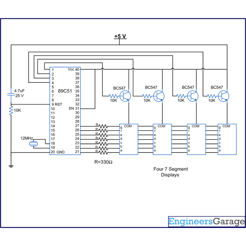
A digital clock displays time in a digital format. The circuit outlined here shows the time with double-digit minutes and two digits for seconds across four seven-segment displays. The segments of the displays are interconnected with the 8051 microcontroller...
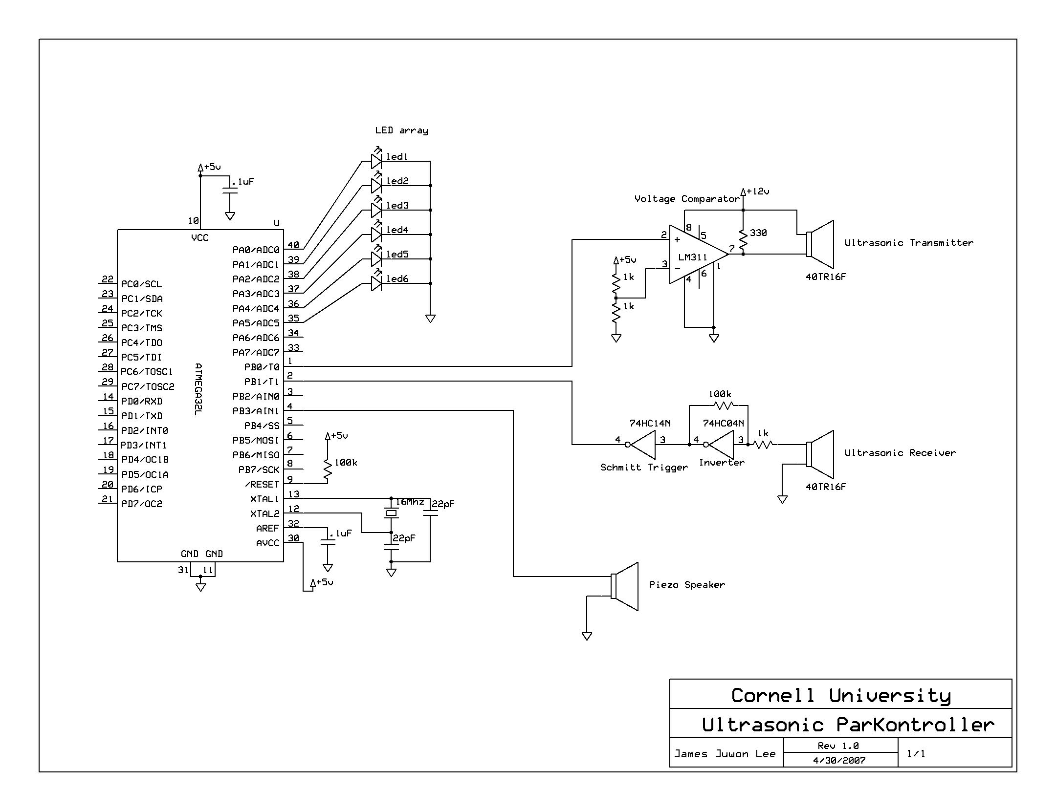
A series of five short pulses blasted by the microcontroller only has 5V amplitude, which will be attenuated down to less than 20 mV when received by the receiver circuit. Hence, LM311 voltage comparator was used for signal amplification...
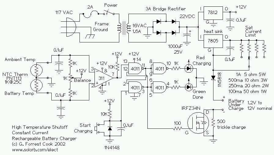
This circuit is designed for a temperature-controlled constant current battery charger, compatible with NiCd, NiMH, and other rechargeable cells. It operates on the principle that most rechargeable batteries exhibit an increase in temperature when they are fully charged. Overcharging...
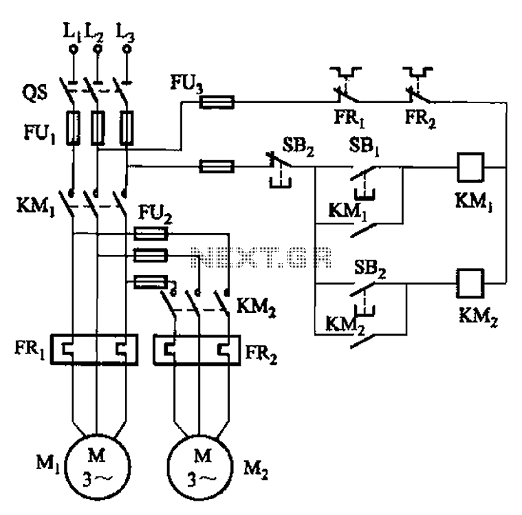
The circuit illustrated in Figure 3-83 demonstrates that the contactor KMi is activated only after it is pulled, which indicates that the motor Mi has started for the first time. Following this, the contactor KM2 is then activated, indicating...
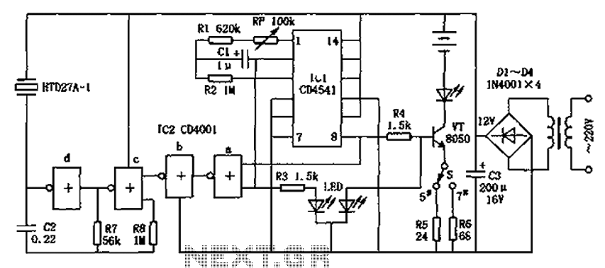
The CD4001/CD4541 nickel-cadmium battery automatic charger circuit is illustrated in the figure. This circuit is designed for charging up to seven rechargeable nickel-cadmium batteries. It features automatic charging with constant current characteristics. Once powered, the circuit activates an internal...
This DC drill speed controller circuit allows for the adjustment of the rotational speed of a drilling machine. A mini-drill machine is always... This circuit utilizes a pulse-width modulation (PWM) technique to control the speed of a DC motor, which...