
Automatically Repeating Interval-Timer Circuit

= The main purpose of R6 is to set an upper limit on the frequency. Its value was chosen to provide a minimum period of about 30 seconds at Pin 7. The value of R7 was chosen to provide a maximum period in excess of 12-hours at Pin 3. This means that the timer can be set to re-trigger at intervals of anything from one minute up to at least 24-hours. = Since the charge on C4 is constantly reversing in polarity - ideally the capacitor should be non-polarized.
However - modern electrolytic capacitors generally have a very low leakage current - even in the reverse direction. So you can usually get away with using a regular polarized electrolytic capacitor. = Because the minimum value of R6 + R7 is 150k - very little current will flow through the resistors.
So - even if C4 does leak in the reverse direction - the worst that can happen is that the oscillator won`t run. = It`s easy to tell if the oscillator is running. Set R7 at about mid-point. If the green LED is turning on and off at about 3-second intervals - the oscillator is working properly.
= Note that R6, R7 & R8 are connected in series between Pins 10 and 11. They join the output of the first inverter to its own input. The value of R8 needs to be very high. That way - any influence the output of the first inverter has on its own input will be very small. It will be swamped by the influence of the changing charges on C4. = The data sheet for the 4060 says that the value of R8 should be at least ten times the value of R6 + R7. A 4M7 resistor was chosen because they`re widely available. It`s possible to use such high value resistors because Cmos inputs are operated by voltage - and not by current.
Because no current flows through the R8 - there`s no voltage drop across it. = The Cmos 4060 is a 14-bit binary counter. The output from the oscillator is connected internally to the counter. And the counter counts the number of oscillations. = As it does so - the state of the count is reflected by the output pins. For example - after 8 oscillations - Bit 4 at Pin 7 will go high. After 16 oscillations - Bit 5 at Pin 5 will go high. After 32 oscillations - Bit 6 at P 🔗 External reference
Related Circuits

The system employs an optical fingerprint sensor utilizing the ARM Cortex M3 core, specifically the STMicroelectronics 32-bit high-performance microcontroller STM32F205RE. It incorporates a function body composition that utilizes the Sobel edge detection operator, Gabor filtering, image binarization, and various...
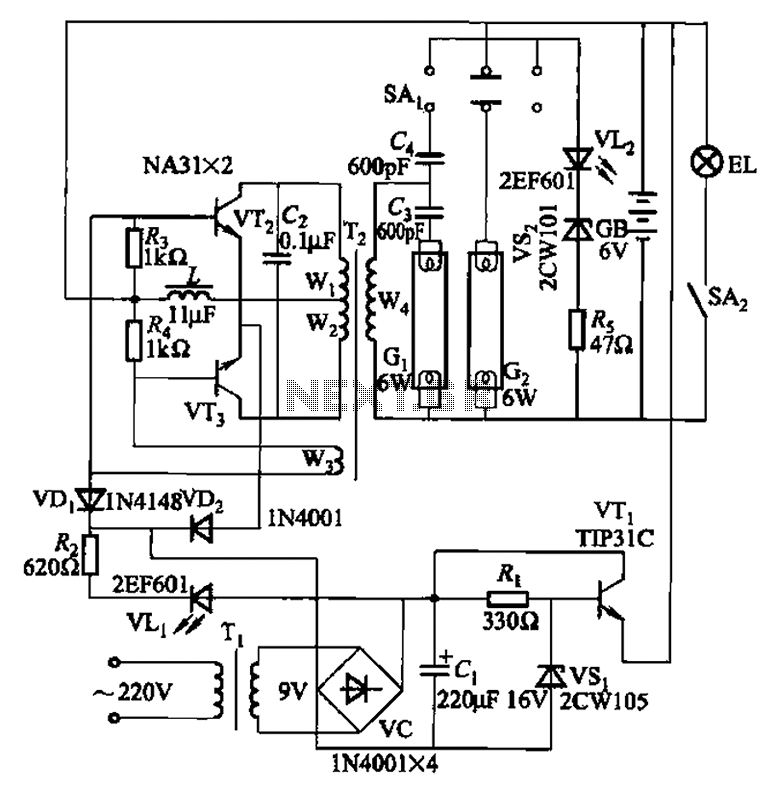
This is a Nissan Panasonic rechargeable emergency fluorescent lamp circuit. It features built-in 6V, 4Ah high-energy batteries that can be directly charged. The circuit supports two 6W fluorescent lamps. It includes functional switches SAi and SAz. When SAi is...
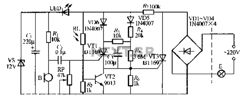
A relatively simple circuit for controlling a stair walkway light with a delay feature. The circuit has a drawback in that the voice activation is somewhat less sensitive, making it sometimes difficult to trigger with general conversation. However, it...
The circuit is a DC to DC converter utilizing a standard 12 VAC center-tapped power transformer configured as a blocking oscillator. Although the circuit exhibits low efficiency, it generates a high voltage suitable for low-power applications. The input battery...
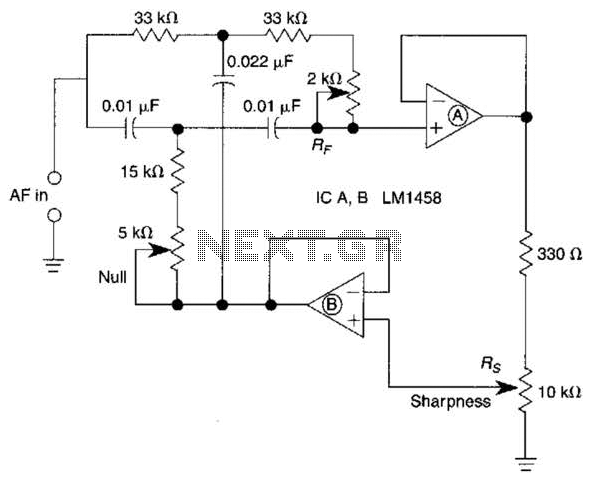
A bootstrapped twin notch filter in this circuit can yield an effective Q of up to 10. Rs adjusts the feedback, hence the Q. Values of C1 and C2 can be changed to alter the frequency. RF is a...
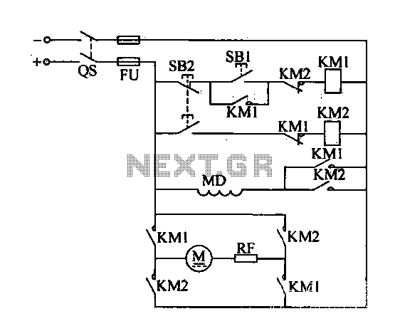
A DC motor reverse brake circuit is presented. To initiate braking, the stop button (SB2) is pressed, which disconnects the move-off contact, causing KM1 to lose power and release. Subsequently, the brake contactor (KM2) is activated. KM2 is designed...