
Jog shuttle function with automatic control circuit

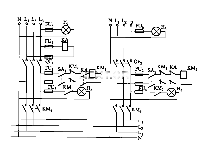
The circuit is designed to facilitate the fine control of mechanical movements through the use of jog buttons. The forward jog button (SB3) and the reverse jog button (SB4) are integral components that enable the user to control the direction of movement. When the forward jog button is activated, it energizes the KM1 relay, which is intended to create a self-locking mechanism. However, the functionality is hindered by the interruption of the normally closed contact of the SB3 button, preventing the KM1 relay from maintaining its state after the button is released.
To further elaborate, the design incorporates a self-locking relay configuration that is typically employed in applications requiring momentary control over a motor or actuator. The relay KM1 is responsible for maintaining the circuit's closed state to allow continuous operation once the jog button has been pressed. The interruption of the normally closed contact serves as a safety feature, ensuring that the system does not inadvertently remain engaged when the jog button is not actively pressed.
In practical applications, this circuit can be utilized in various systems where precise positioning is critical, such as in CNC machines, automated assembly lines, or robotic arms. The jog feature enhances operational flexibility, allowing operators to make fine adjustments without the need for complex programming or manual intervention. The careful consideration of relay contacts and button configurations is essential in ensuring reliable performance and user safety in such applications. Circuit shown in Figure 3-27. Jog feature is available for fine adjustment of moving parts. Figure, SB3 and SB4 are forward jog and reverse jog button button. When you press th e SB3 time, KM1 self-locking contact, although closed, but because SB3 normally closed contact has been disconnected, it can not self-locking.
Related Circuits
Dual power automatic recovery means one power supply and one standby power supply. When the main power supply is turned off, the standby power supply is automatically activated. Once the main power supply is restored, the system automatically exits...
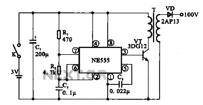
This circuit illustrates a simple boost converter, which is powered by an oscillating signal generated by the NE555 timer. The signal is amplified through a VT transistor to drive a booster transformer. This step-up transformer increases the oscillating signal,...
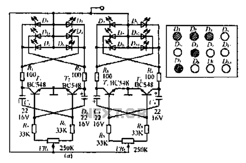
A circuit involving oscillations is composed of a Houle Wang oscillator that utilizes a transistor configuration with components labeled Ti, n, and n, along with a composition of Q constants for the cycle. The waveform can be modified by...
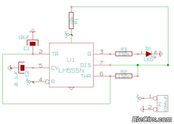
This is a very simple 555 timer circuit that serves as a straightforward theft deterrent, which may be just as effective. The idea is to have a flashing red LED indicate that your car is protected. This device can...
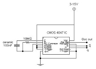
This circuit generates a digital square wave that can be displayed directly or utilized to drive additional circuits. It employs the CMOS 4047 Low-Power Monostable/Astable Multivibrator, as referenced in Tom Duncan's "Adventures with Digital Electronics" book, to control a...
An LED is usually a series resistor needed to ensure that the LED does not get too much power. The disadvantage of such resistance is that the current through the LED and thus the brightness changes as the voltage...