
The use of a motor control switch automatic circuit a mutual investment

The circuit described operates through a series of interlocked switches that facilitate automatic and manual control of two motors, Mi and M2. In the automatic mode, the system ensures that when one motor is running, the other is on standby, thus providing redundancy and reliability. The configuration allows for seamless operation; if the primary motor fails or requires maintenance, the secondary motor can take over without manual intervention, minimizing downtime.
The specific switches utilized, LW5-15D0404/2, are designed for durability and reliability in industrial applications, ensuring that the circuit can handle the operational demands placed upon it. The manual control feature adds flexibility, allowing operators to start or stop each motor independently based on operational requirements. This capability is particularly useful in scenarios where one motor may need to be serviced while the other continues to operate.
The design of the circuit emphasizes safety and efficiency. By incorporating automatic transfer capabilities, it reduces the risk of system failure due to motor downtime. The interlock mechanism prevents both motors from running simultaneously, which could lead to overload conditions. Overall, this circuit design is well-suited for applications requiring high availability and operational flexibility in motor control. Circuit shown in Figure 3-64. When the switch SAi placed in the work position, SA2 placed in the standby position, the motor is running Mi, Mz spare. When downtime occurs when Mi, Mz automatically put into operation; similarly, SAz into work position, SAi placed in the standby position, the M2 run, Mi spare, when downtime occurs when M2, Mi automatically put into operation. When SAi and SA2 are placed in the manual position, you can separately Mi, M2 motor manual control. SAi and SA2 can type LW5-15D0404/2 transfer switch.
Related Circuits
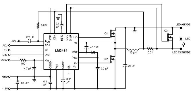
The LM3434 adaptive constant on-time DC/DC buck (step-down) constant current controller can be used to design a simple high-power LED driver application. The LM3434 provides a constant current for illuminating high-power LEDs. The output configuration allows the anodes of...
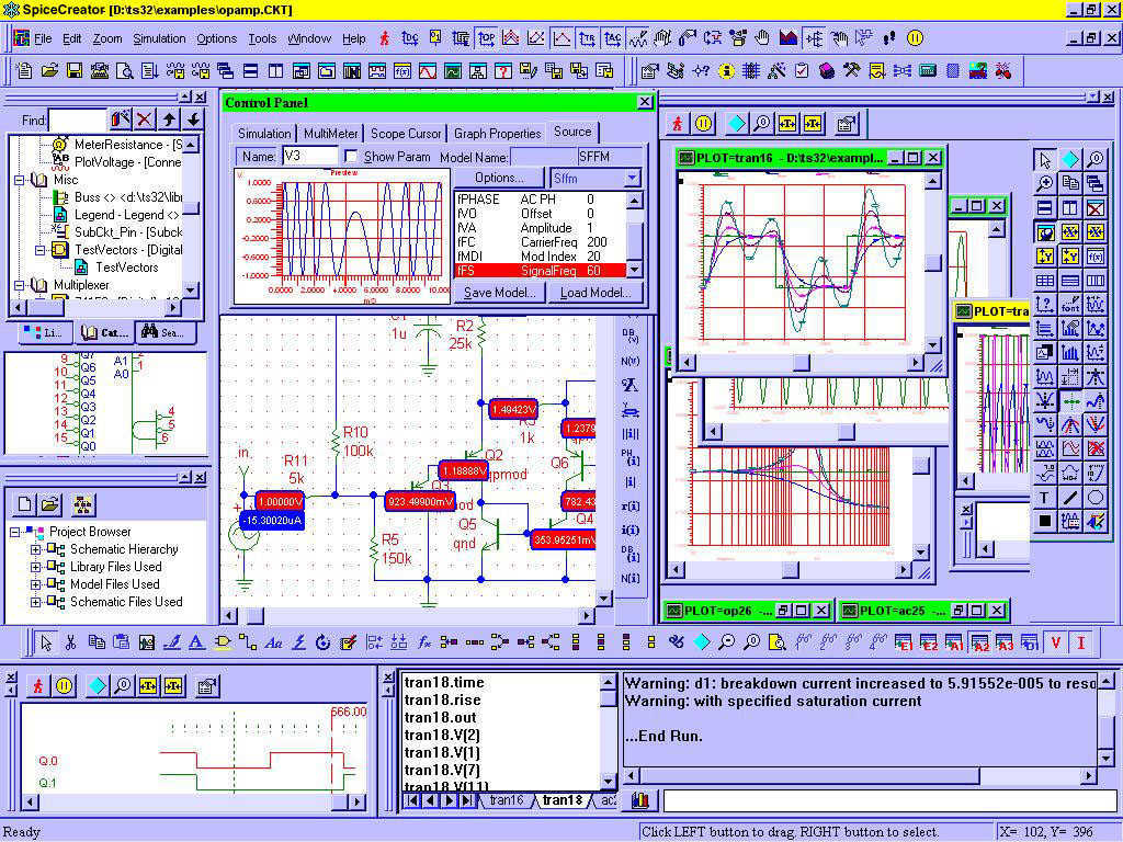
Circuit CREATOR Electronics CAE System provides the most complete and high performance solution for electronics design using personal computers. More: Includes PCB DESIGN -layout editor and Schematic Capture software tool, full Schematic Design and Capture, Circuit Simulation, full interactive...
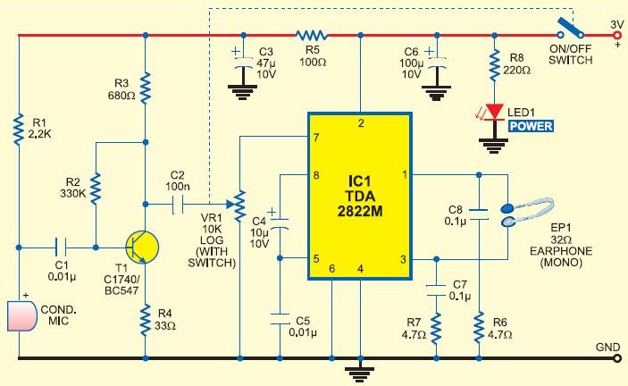
This is a cost-effective DIY option for a hearing aid. It should not be considered a replacement for a genuine hearing aid prescribed by an audiologist. Amplifying all sounds and frequencies, or using it continuously in loud environments, may...
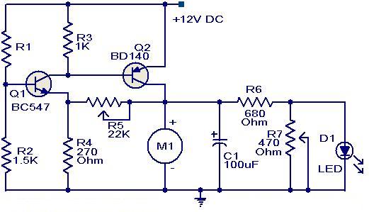
This circuit utilizes two transistors to control the speed of a 12 V DC fan based on temperature variations. A thermistor (R1) is used to sense the temperature. As the temperature rises, the base current of Q1 (BC 547)...
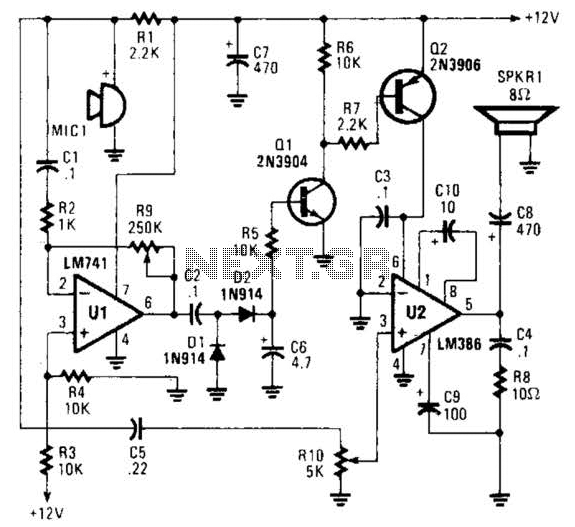
An omnidirectional electret microphone is utilized to capture sound and convert it into an electrical signal. The output from the microphone is directed along two pathways. In the first pathway, the signal is routed to the inverting input at pin...
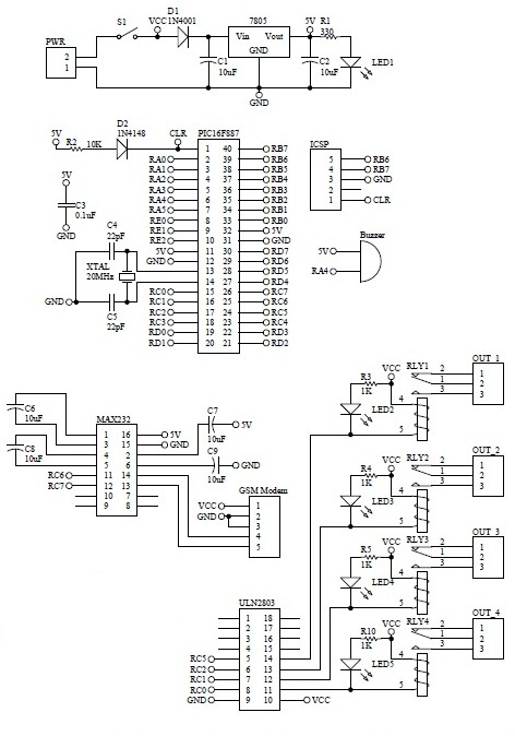
How to turn on equipment by sending SMS `1111` to switch it ON and switch off the equipment by sending SMS `0000`. The GSM switch will receive instructions for either load 1 (L1), load 2 (L2), load 3 (L3),...