
Hearing Aids Circuit

This hearing aid circuit provides a practical solution for individuals experiencing mild to moderate hearing loss. The design includes a condenser microphone that captures sound waves and converts them into electrical signals. These signals are amplified by the transistor T1, which serves as the preamplifier, enhancing the acoustic signals before they are sent to the main amplifier section.
The TDA2822M IC functions as a medium-power amplifier capable of driving low-impedance earphones, making it ideal for portable applications. The bridge configuration allows for increased output power, ensuring that the user experiences sufficient sound levels.
The circuit's low power consumption is a significant advantage, as it operates on a minimal quiescent current, allowing for prolonged usage without frequent battery replacement. This feature is particularly beneficial for users who may rely on the device for extended periods.
Assembly on a veroboard is straightforward, and the use of an IC socket for the TDA2822M not only simplifies the initial construction but also facilitates any future repairs or replacements. Overall, this DIY hearing aid circuit represents an accessible and effective alternative for those in need of auditory assistance while awaiting more advanced solutions.This is a less expensive, and DIY option for a hearing aid. It is not a substitute for a real hearing aid that an audiologist would prescribe. Amplification of all sounds and frequencies, or constant use in loud environments can cause additional hearing loss. This circuit could be helpful for some types of hearing loss and occasional use, as well as fill in during the average amount of time people wait to get a hearing aid (7 years). This low-cost, general-purpose electronic circuit works off 3V DC (2G—1. 5V battery). Transistor T1 and associated components form the audio signal preamplifier for the acoustic signals picked up by the condenser microphone and converted into corresponding electrical signals. Medical grade hearing aids are very expensive, if a person needs help hearing but not necessarily the full cost and capability of a prescribed hearing aid, this might be an option.
The medium-power amplifier section is wired around popular audio amplifier IC TDA2822M (not TDA2822). This IC, specially designed for portable low-power applications, is readily available in 8-pin mini DIP package.
Here the IC is wired in bridge configuration to drive the 32-ohm general-purpose monophonic earphone. The audio output of this aid circuit is 10 to 15 mW and the quiescent current drain is below 1 mA. The circuit can be easily assembled on a veroboard. For easy assembling and maintenance, use an 8-pin DIP IC socket for TDA2822M. 🔗 External reference
Related Circuits
A 35W resistive and capacitive half-wave phase-shift trigger control circuit is designed for automatic or semi-automatic welding equipment to manage wire feeding and welding carriage travel. This system necessitates a drive control circuit to fulfill the welding process requirements....
At dawn, light illuminates the photosensitive resistor RL, causing its resistance to decrease. This switch IC (2) exhibits a high electrical footprint. When light is present, the relay K does not activate. At night, in the absence of light,...
A simple musical light chaser circuit diagram and schematic using IC CD4016. This circuit blinks lights in response to sound, audio, or music output, causing 10 lights to dance according to sound frequency. The musical light chaser circuit utilizing the...
The resistors were not measured precisely, and given their ±5% tolerance, along with a Vref range of 1.2 to 1.3 volts, it is possible to exceed 6 volts in certain scenarios. A discussion arose regarding the effectiveness of these...
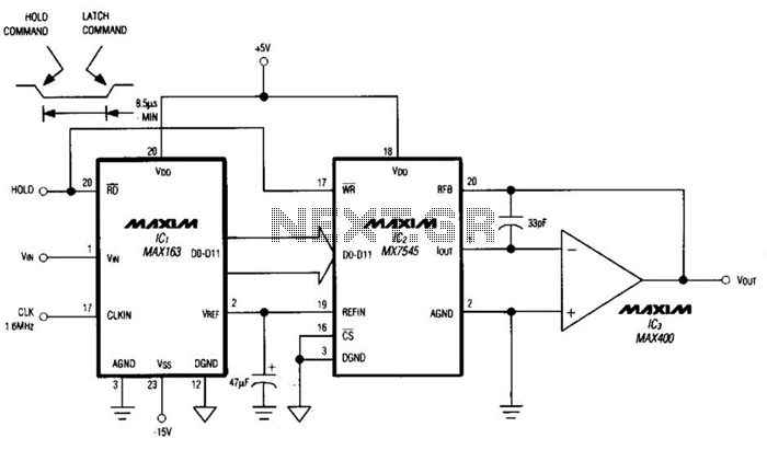
Driving a D/A converter using an A/D converter provides an overall analog-hold function. Although this function has limitations in output resolution, it offers zero voltage droop and infinite hold time. The A/D converter depicted (IC1) features a 12-bit compatible...
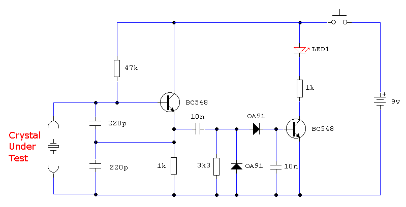
In the first circuit, the BC548 transistor is configured as a Colpitts oscillator, with the frequency being adjusted through the insertion of a crystal. A high-quality crystal will generate high-frequency oscillations, and the output at the collector is rectified...