
AC motor control
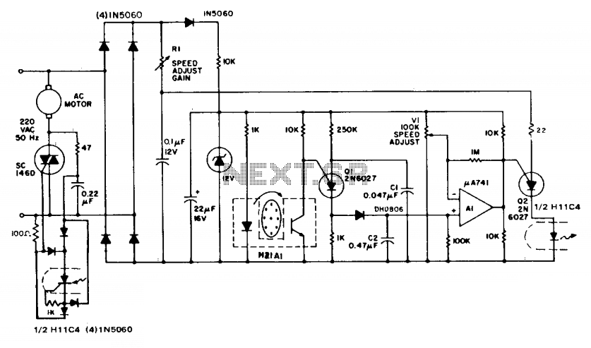
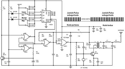
The described circuit employs a feedback mechanism to regulate the speed of an AC induction motor effectively. The key components involved include the apertured disc, which serves as a rotational speed detector, and the interrupter module that generates a light beam. As the motor rotates, the disc interrupts the beam, enabling the detection of the motor's speed through the discharge of capacitor C1. The programmable unijunction transistor (Q1) plays a crucial role in this process by controlling the discharge of C1 into the larger capacitor C2, which accumulates charge proportional to the motor's speed.
The operational amplifier (A1) is configured to compare the voltage on C2, which reflects the motor speed, against a reference voltage (V1). This comparison is essential for determining whether the motor speed is above or below the desired setpoint. The output from A1 translates this comparison into a DC control signal that modulates the second programmable unijunction transistor (Q2). This transistor is synchronized with the AC supply frequency, ensuring that the control signals are in phase with the power supply.
The triac, being the final control element in the circuit, receives trigger pulses from Q2. The timing of these pulses is critical, as it dictates the phase angle at which the triac conducts. The phase angle is influenced by the speed control resistor (R1) and the actual speed detected by the system. By adjusting R1, the user can fine-tune the motor speed, allowing for precise control over the motor's operation.
Overall, this circuit provides an effective and cost-efficient solution for speed regulation in AC induction motors, eliminating the need for expensive tachometers while maintaining accuracy and responsiveness in speed control.The circuit illustrates feedback speed regulation of a standard ac induction motor, a function difficult to accomplish other than with a costly, generator type, precision tachometer. When the apertured disc attached to the motor shaft allows the light beam to cross the interrupter module, the programmable unijunction transistor, Ql, discharges capacitor, Cl, into the much larger storage capacitor, C2.
The voltage on C2 is a direct function of the rotational speed of the motor. Subsequently, this speed-related potential is compared against an adjustable reference voltage, VI, through the monolithic operational amplifier, Al, whose output, in turn, establishes a dc control input to the second P.U.T. (Q2). This latter device is synchronized to the ac supply frequency and furnishes trigger pulses in the conventional manner to the triac at a phase angle determined by the speed control, Rl, and by the actual speed of the motor. 🔗 External reference
Related Circuits
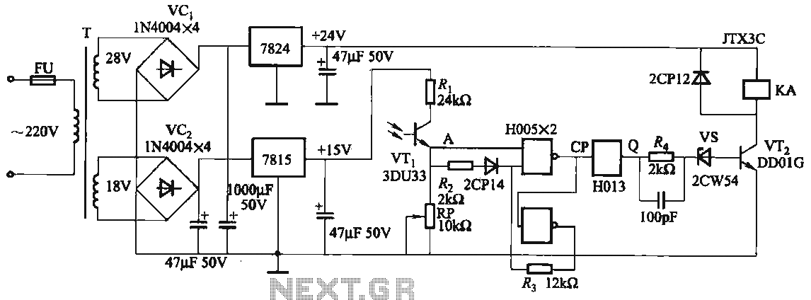
The circuit features a robust anti-jamming capability, making it suitable for demanding applications. It includes a phototransistor (VTi), a Schmitt trigger (H005), a JK flip-flop (H013), a power amplifier circuit, a relay (KA), and various actuators and other components....
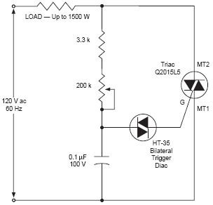
The DIAC, or diode for alternating current, is a trigger diode that conducts current only after its breakdown voltage has been momentarily exceeded. Most DIACs are utilized in applications requiring a switching function in AC circuits. The DIAC is a...
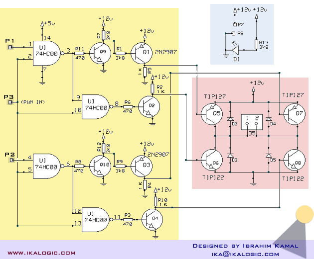
A relatively high-power H-bridge motor controller, which is a common method to control DC motors, utilizes inexpensive TIP transistors. A continuous current of 5 Amperes through an H-bridge module may not seem significant to some, depending on their background...
The following circuit illustrates a schematic diagram for a remote control toy car. Features: it does not interfere with the performance of the original design. The remote control toy car circuit typically consists of several key components that enable wireless...
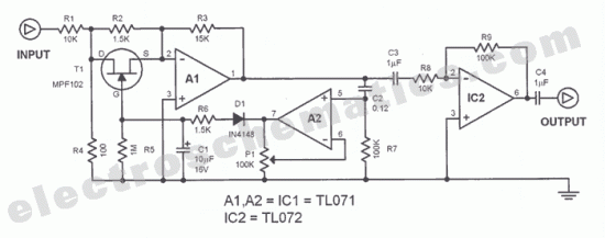
The function of this automatic volume control circuit is to amplify signals without distorting their dynamic compression. The amplitude differences in the signal are leveled off, eliminating disturbing effects. This technique avoids overcompensation in volume. The circuit is utilized...
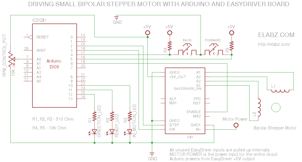
A simple circuit designed for testing bipolar stepper motors or for manual positioning using stepper motors. Schematics, Arduino sketch, and video are available. This circuit serves as a versatile tool for both testing and controlling bipolar stepper motors, which are...