
Remote Control Toy Car Schematic

The remote control toy car circuit typically consists of several key components that enable wireless control and operation. The main elements include a transmitter, a receiver, a motor driver, and the toy car's DC motors.
The transmitter is generally equipped with a control interface, such as a joystick or buttons, which sends radio frequency (RF) signals to the receiver. The transmitter circuit may include a microcontroller that processes user inputs and modulates the RF signal for transmission.
The receiver, located within the toy car, is designed to decode the incoming RF signals. It usually incorporates a demodulator and a microcontroller that interprets the commands and controls the motor driver accordingly.
The motor driver is a crucial component that interfaces between the receiver and the DC motors. It amplifies the control signals from the receiver and provides the necessary current to drive the motors. Commonly, an H-bridge configuration is used, allowing for bidirectional control of the motors, which enables forward, reverse, and turning maneuvers.
The DC motors are responsible for propelling the toy car. They are typically equipped with gear systems to enhance torque and speed. Power for the entire circuit is usually supplied by a battery pack, which must be adequately rated to ensure sufficient operational time and performance.
Overall, the remote control toy car circuit is designed to be user-friendly, providing a seamless interface for operation while maintaining the integrity of the original toy's performance. The careful selection and integration of components are essential to ensure reliability and responsiveness in the toy car's movements.The following circuit shows about Remote Control Toy Car Schematic Circuit Diagram. Features: does not impose on the performance of the original .. 🔗 External reference
Related Circuits
The Car Voltage Gauge is based on 3 parts. The input circuit is an Analog to Digital Converter (IC2 CA3162E). The purpose of this chip is to sample an analog voltage and convert it to a decimal value which...
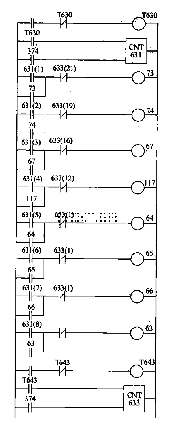
Based on the system characteristics, a drum controller is utilized to meet the specified requirements, with the design of the ladder as illustrated in the accompanying figure. 1) C631 and C633 function as a drum controller, counting pulses generated...
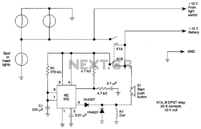
Pressing the START pushbutton activates either the headlights or spotlights for a specified duration. After 1 minute, determined by R1 and C1, the lights will turn off as the NE555 timer completes its cycle. The circuit utilizes a NE555 timer...
This Project is used to indicate the temperature and it is also used as controller. The system will get the temperature from the IC and it will display the temperature over the seven segment display and this temperature was...
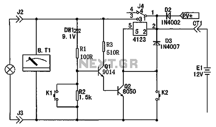
The circuit depicted in the figure consists of a battery, a controller, and various electrical and charging components. It includes a Zener diode (D1) and resistors (R1, R2) for undervoltage detection. The circuit also features transistors (Q1, Q2), resistors...
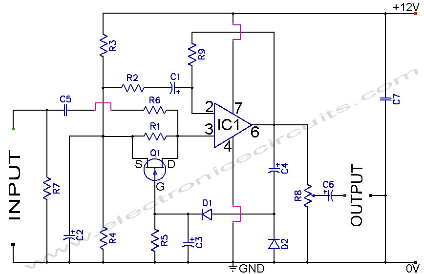
A section of the operational amplifier's output signal is rectified using 1N4148 diodes, followed by filtering, and is then directed to the gate of the FET input shunting circuit. As the output voltage increases, additional input shunting occurs, which...