
Build a 5A H-bridge Motor driver! Old version

The H-bridge motor controller is designed to provide efficient control of DC motors by allowing bidirectional rotation and speed regulation. The configuration employs four transistors arranged in a bridge format. The two pairs of transistors on either side of the bridge are responsible for reversing the polarity of the voltage applied to the motor, thus changing its direction of rotation.
When implementing this circuit, it is essential to ensure that the transistors are adequately rated for the current and voltage specifications of the motor being controlled. The TIP transistors typically have a maximum collector current rating that should not be exceeded to prevent overheating and potential damage. Additionally, heat sinks may be required to dissipate excess heat generated during operation.
The control signals for the H-bridge can be generated using a microcontroller, such as an Arduino or Raspberry Pi, which sends PWM (Pulse Width Modulation) signals to the base of the transistors. This technique allows for fine control over the motor speed by varying the duty cycle of the PWM signal. The duty cycle determines the average voltage and current supplied to the motor, thereby controlling its speed and torque output.
In summary, the H-bridge motor controller using TIP transistors is a robust solution for hobbyists and engineers looking to control DC motors with precision. Understanding the operation of transistors and their role in the H-bridge configuration is crucial for building efficient motor control systems. Proper design considerations, including component selection and thermal management, will ensure reliable and effective motor operation.A relatively High power H-bridge motor controller (which is the most common way to control DC motors) With cheap TIP transistors. 5 Amperes of continuous current through an H-bridge module may not seen high power to someof you, depending on your field and experience, that`s why I used the word relatively.
But in the field of hobby electronics and robotics, yes a controller capable of controlling motors with currents as high as 5A at 24V is considered a high power device. The H-bridge is principally a configuration of four switches, that are switched in a specific manner to control the direction the of the current through the motor. (For brushed DC motors, the direction of rotation of the armature of the motor is changed by changing the direction of the current flowing though it).
While we are talking about DC motors, here is a small useful note to bear in mind: Current flowing though a motor is proportional to the output torque, while the angular velocity (rpm) of the the output shaft is proportional to the the voltage across the motor windings . Below figure 1, is a simplified diagram showing the operation of the H-bridge configuration(you can notice the shape of the schematic, it looks like an H` letter, this is how this famous circuit got this name!).
There are two possible paths for the current: The only difference between this simple H-bridge and the real H-bridge module explained on this page, is that the switches are replaced by Transistors, in order to electronically control the flow of current in the motor, hence, allowing us tocontrol the speed and direction of the motor from a microcontroller, for example. In case you are a beginner or just not familiar with transistors, I am going to explain in the next section most of what you need to know about transistors to understand and build an H-bridge.
One very simple way to use transistors is to use them as switches, to electronically control the flow of current though other electrical elements. The same transistor may be used as a signal amplifier, but this is the messy part of the transistor studies, and we don`t need this for our H-bridge.
Using transistors as a switch is also called using transistors in saturation and cut-off mode. This schematicfigure 2, simply shows the meaning of using a transistor as a switch. The only difference between a mechanical switch and a transistor switch is that a normal switch is turned ON or OFF mechanically while a transistor switch is turned ON and OFF using smallelectrical currents applied on the Base, usually smaller than 20 mA. For an NPN transistor, when a small current flows into the Base of the transistor, current will flow from the Collector to the Emitter, otherwise, no current will through the CE junction (Collector-Emitter junction).
On the other hand, for a PNP transistor, when a small current is allowed out from the base of the transistor, current will flow from the Emitter to the Collector. In order to use the transistor as a switch, the base voltage has to beHigher than the Collector voltage (in case of NPN transistor), or Lower than the collector voltage (in case of PNP transistor).
Also, to ensure the transistor is saturated, you must calculate the suitable value of Rb shown in the schematic (this will be discussed in detail later ). You may wonder why are there two different implementations of the Transistor switch, one with NPN transistor, the other with a PNP one.
The answer is very simple, it is to ensure that the base voltage is at a suitable level to ensure the transistor is saturated whether it is connected to ground or to 12V. (in the H bridge, two transistors are connected to 12V, while the two others are connected to Ground.
) Depending on the transistor you are using, gather from the datasheet the following values. sometimes for beginners, finding those values in the datasheet, or the near 🔗 External reference
Related Circuits
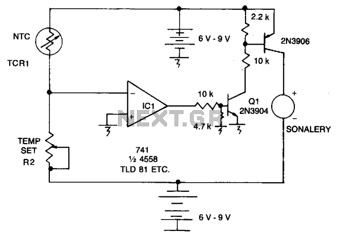
As the resistance (Rl) increases with a decrease in temperature, the output of integrated circuit IC1 becomes positive, activating transistor Q1. When Q1 conducts, it also triggers transistor Q2, which in turn activates the audible alarm. The threshold level...
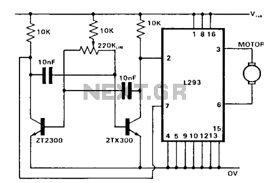
The control of both direction and proportional motor speed is accomplished through the rotation of a single potentiometer. The motor driver utilized is the SGS integrated circuit L293, which can drive up to 1 amp in either direction, depending...
This is a reverse-engineered circuit diagram of a one-transistor circuit commonly used to drive permanent magnet DC motors in children's toys. This circuit typically employs the 625mW version of the widely used 8050 or 8550 transistor. It is important...
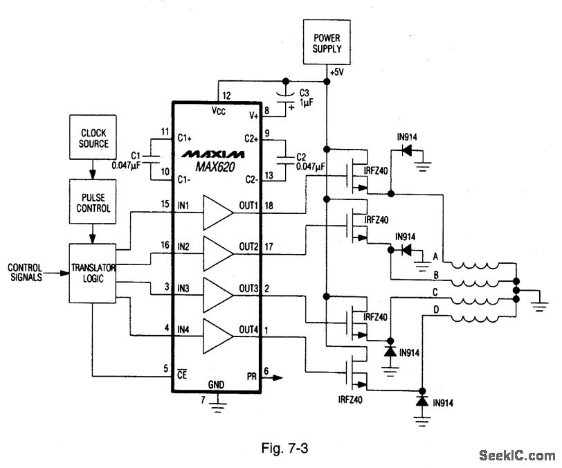
A MAX620 is connected to create a complete stepper motor drive system. TTL/CMOS signals from the logic network are converted to high-side levels that control four N-channel power MOSFETs, which supply current to each of the four phases of...
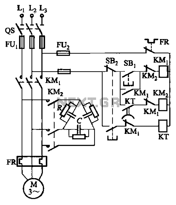
The circuit illustrated in Figure 3-151 consists of capacitor banks arranged in a specific configuration. Figure 3-151 (a) depicts capacitor banks connected in a shaped manner, which is suitable for use with shaped or Y-connected motors. Figure 3-151 (b)...
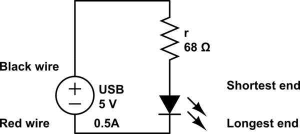
The LED operates at 3V, and based on information available online, a blue LED typically supports a maximum current of 0.03A. Given the available current from the USB source, the intention is to construct a parallel circuit. However, the...