
Photoelectric controller circuit immunity

The circuit design incorporates a phototransistor (VTi) that serves as a light sensor, detecting ambient light levels. When light is present, the phototransistor conducts, triggering the Schmitt trigger (H005) to provide a clean digital signal. This signal is then fed into a JK flip-flop (H013), which is configured to toggle the state of its output based on the input signal from the Schmitt trigger. The JK flip-flop's output controls a power amplifier circuit, which drives the relay (KA).
The relay (KA) acts as a switching mechanism that connects or disconnects the load based on the light conditions detected by the phototransistor. When the phototransistor is illuminated, the relay is energized, closing the circuit and allowing current to flow to the connected actuators or other components. Conversely, in the absence of light, the relay deactivates, interrupting the current flow.
The adjustment potentiometer (RP) plays a crucial role in fine-tuning the circuit's operational parameters. It allows the user to set the voltage levels at points A and B, ensuring that point A maintains a high potential greater than 8V, while point B remains below 7V. This precise adjustment is essential for the reliable operation of the circuit, as it establishes the thresholds for the Schmitt trigger and ensures consistent performance in varying light conditions.
Overall, this circuit design is well-suited for applications requiring reliable light detection and switching capabilities, with built-in features to mitigate interference and enhance performance in challenging environments.It has a strong anti-jamming capability, suitable for demanding applications. Circuit by the phototransistor VTi, Schmitt trigger H005, JK flip-flop H013, power amplifier circuit VTz relay KA and actuators and other components. When phototransistor VTi by light, relay KA pull; when there is no light, KA released. Adjustment potentiometer RP, ensure high potential point A is greater than 8V, A low potential point less than 7V, the circuit can work properly.
Related Circuits
The bearing fault detector circuit consists of a bearing detection sensor, a signal processing circuit, a transistor (V), an audio amplifier integrated circuit (IC2), a speaker (BL), an RC element, an integrated circuit (IC1), and a light-emitting diode (VL)....
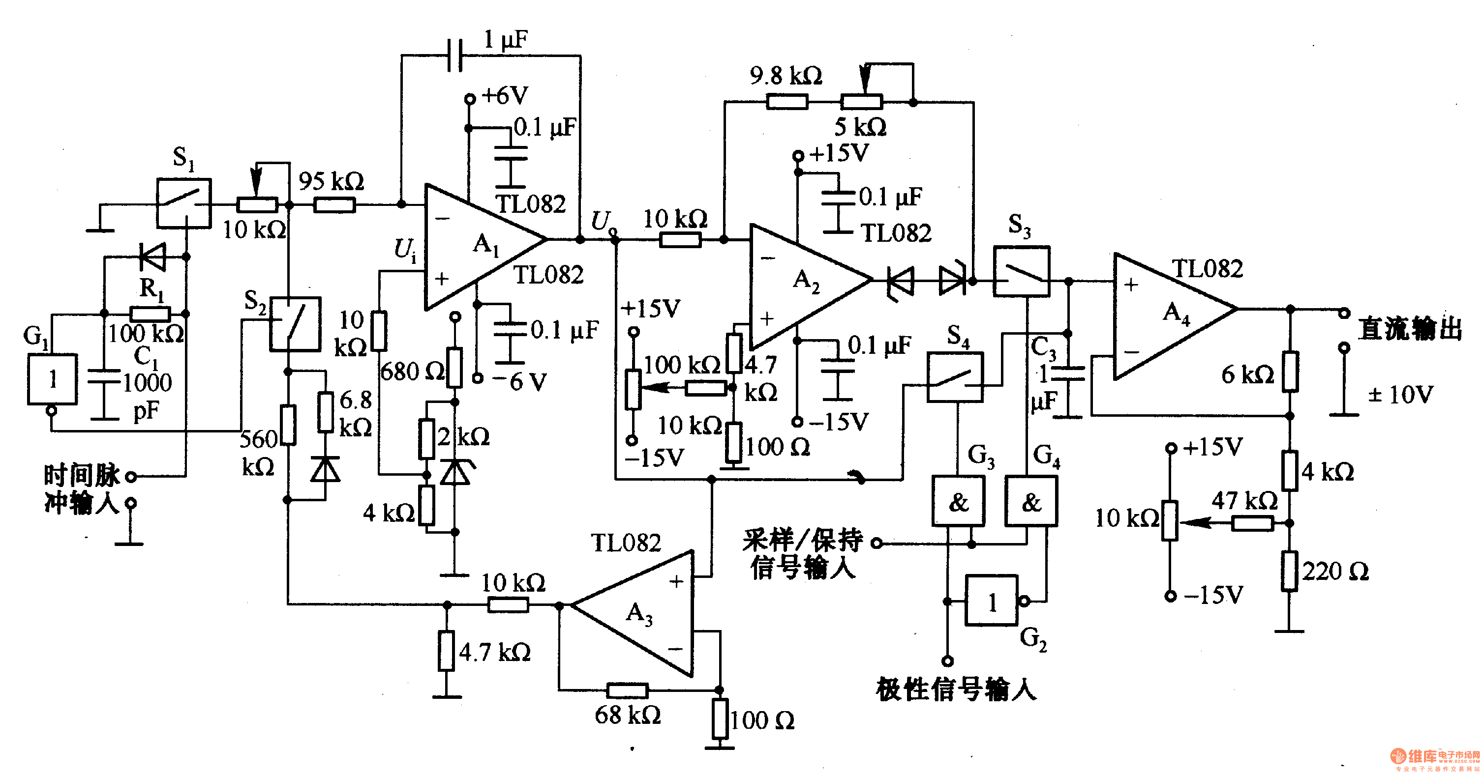
This circuit is designed for pulse width (time) to voltage conversion. According to the component parameters in the diagram, it can convert a pulse width of 0.1 seconds into an output voltage of 10V. When a conversion pulse is...
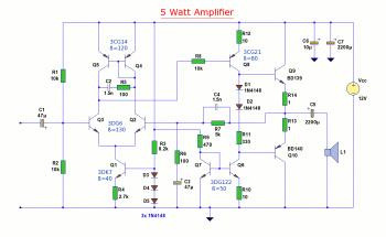
The diagram illustrates a 5W audio amplifier circuit constructed using power transistors BD139 and BD140 for the final amplification stage. This compact amplifier serves as a general-purpose amplifier suitable for applications such as computer audio, radio, MP3 players, and...
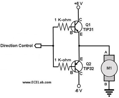
The following circuit illustrates a two-transistor DC motor driver circuit diagram. This circuit utilizes the TIP32 transistor. Features: operates in... The two-transistor DC motor driver circuit is designed to control the operation of a DC motor using two NPN transistors,...
The total gain of the car antenna amplifier is approximately 30 dB, with an input impedance of around 10 kΩ at 30 MHz. The amplifier should be mounted directly at the base of the antenna to prevent signal losses...
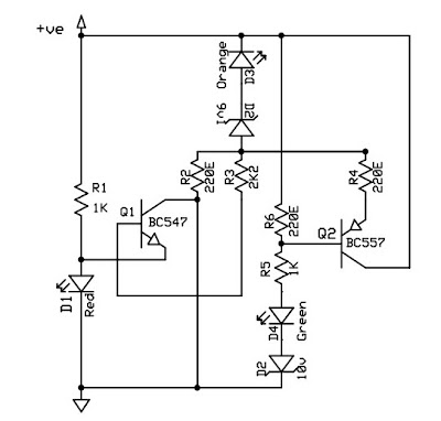
This circuit is a 12V battery checker that utilizes three LEDs to indicate different voltage levels. The red LED illuminates when the battery voltage is between 8V and 10V, the orange LED activates at voltages ranging from 10.5V to...