
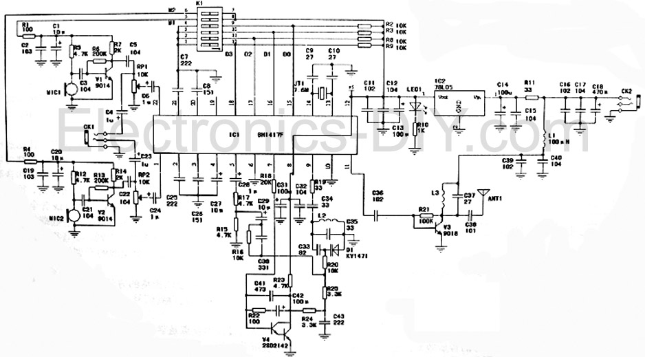
433 MHz 4-ch receiver with relay output transmitter
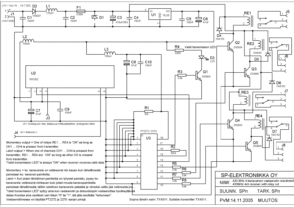
This circuit description pertains to a wireless relay control system utilizing a transmitter and receiver setup. The system features four channels (CH1 to CH4), each corresponding to a relay output (RE1 to RE4).
In the momentary output mode, when a button on the transmitter corresponding to any of the channels (CH1 to CH4) is pressed, the associated relay (RE1 to RE4) activates. This state remains until the button is released, allowing for temporary control over the connected load or device.
The latch output mode allows for a more sustained activation of the relays. When a button on the transmitter is pressed, the corresponding relay is activated and will remain in this state as long as at least one other channel button is held down. This feature enables a more complex control scheme where multiple relays can be activated simultaneously, providing flexibility in controlling multiple devices or systems.
An important aspect of the design is the valid transmission indicator, which is represented by an LED. This LED remains illuminated whenever the receiver successfully receives data from the transmitter, providing a visual confirmation of operational status and aiding in troubleshooting by indicating whether the system is functioning correctly.
Overall, this circuit effectively combines momentary and latch control functionalities while ensuring reliable feedback through the LED indicator, making it suitable for various applications requiring remote relay activation.Momentary output : One of the relays RE1...RE4 is ON as long as CH1---CH4 is pressed from transmitter. Latch output: when one of channels CH1...CH4 is pressed from transmitter RE1...RE4 are ON as long as other CH is pressed from transmitter.
Valid transmission indicator: LED is always on when reciever recieves valid data. 🔗 External reference
Related Circuits
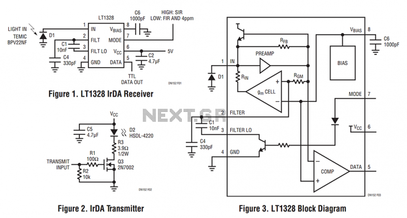
The LT1328, in the MS8 and SO-8 packages, contains all the necessary circuitry to convert current pulses from an external photodiode to a digital TTL output while rejecting unwanted lower frequency interference. The LT1328 plus five external components is...
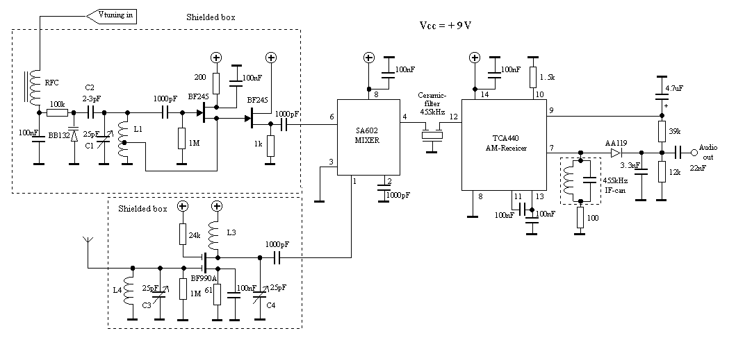
The aircraft communication in Sweden is still Amplitude Modulated (AM). The local airport (Axamo) uses the frequency 118.250 MHz. The receiver is a tunable AM-receiver for this frequency. The receiver is manually tunable within approximately 100 kHz around the...
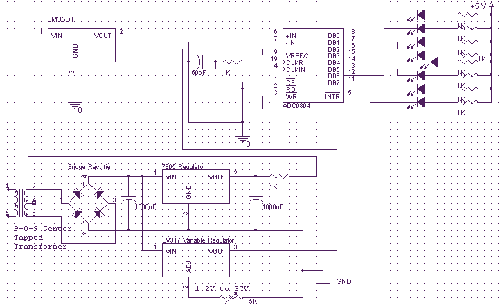
This is a very simple to implement Temperature Sensor. It uses LM35DT as a semiconductor temperature sensor which operates with a +5 volt DC. It produces an analog output voltage, proportional to the change in surrounding temperature in Celsius...
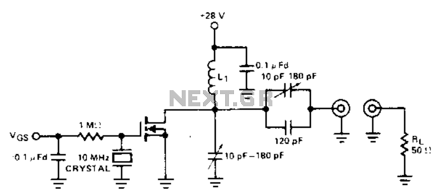
This crystal oscillator is a FET equivalent of a vacuum tube tuned to a plate-tuned grid crystal oscillator. Feedback is achieved through the drain to gate capacitance. The described crystal oscillator utilizes a Field Effect Transistor (FET) to replicate the...
This is a high-fidelity stereo PLL FM transmitter designed for various audio sources including computers, sound cards, game consoles, CDs, DVDs, MP3 players, and stereo mixers. The board features two microphone amplifiers, enabling high-fidelity FM stereo radio transmission when...
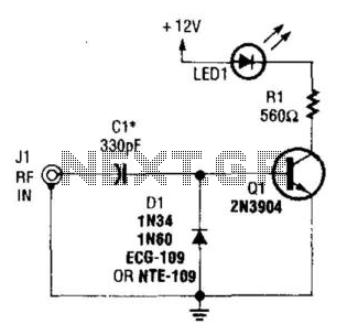
A simple RF detector circuit utilizing a visual indicator can serve as an RF output indicator. This circuit was designed for use as a transmitter ON indicator. The RF detector circuit typically consists of a few key components: a diode,...