
Automobile AM radio circuit

The circuit is designed to facilitate the reception of medium wave radio frequencies, which are essential for AM broadcasting. The use of a tunable diode, such as the BB113, allows for precise frequency adjustment, enabling the user to select different radio stations within the specified frequency bands. The loop tuning method enhances selectivity and sensitivity, which is critical for clear audio reception in automotive environments where interference can be prevalent.
The main coils are integral to the circuit's performance. The coils L1 and L2, both with 122 turns, serve as the primary inductors for tuning and signal amplification. L3, with 68 turns, may act as a secondary inductor to improve the overall gain of the circuit. Coupling coils L5 and L6, with 96 and 64 turns respectively, are designed to transfer energy between different stages of the circuit while maintaining impedance matching, which is crucial for minimizing signal loss.
The wire specifications, using 8 × 0.03 mm copper, indicate a focus on minimizing resistive losses within the coils, which is essential for maintaining signal integrity. The additional coil L7, with 90 turns, may be used for further tuning or as part of a feedback loop to stabilize the circuit's operation.
Overall, this car radio circuit exemplifies a well-thought-out design that balances performance and efficiency, making it suitable for automotive applications where reliable radio reception is necessary.This circuit shows the high and mid part of car radio, and the medium wave band I is 520 ~ 950kHz, Poland II is 900 ~ 1640kHz. Loop tuning uses tunable diode BB113.Main coil data:L1: 122 turns; L2: 122 turns ; L3: 68 turns ; L5: 96 turns ( coupling coil with 7 turns ); L6: 64 turns ( coupling coil with 5 turns).
L1 ~ L6 use 8 × 0.03 copper.L7: 90 turns, 6.. 🔗 External reference
Related Circuits
The circuit was designed to illustrate the use of a tone control circuit, which adjusts audio signals before they are sent to any output device. The tone control circuit serves as an essential component in audio processing systems, allowing for...
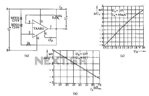
The regulator circuit adjusts the output voltage based on the potentiometer Rp and exhibits linear regulation characteristics. The output voltage Ua varies with the load current Ia, ranging from 0 to 70 mA, as illustrated in Figure (C) for...
This is a small circuit designed as an insect repellent, targeting mosquitoes and birds by producing high-frequency audio signals. These signals interfere with the hearing of insects, making it unbearable for them, causing them to flee. The operation of...
The circuit of automatic emergency light presented here has the following features: 1. When the mains supply (230V AC) is available, it charges a 12V battery up to 13.5V and then the battery is disconnected from the charging section....
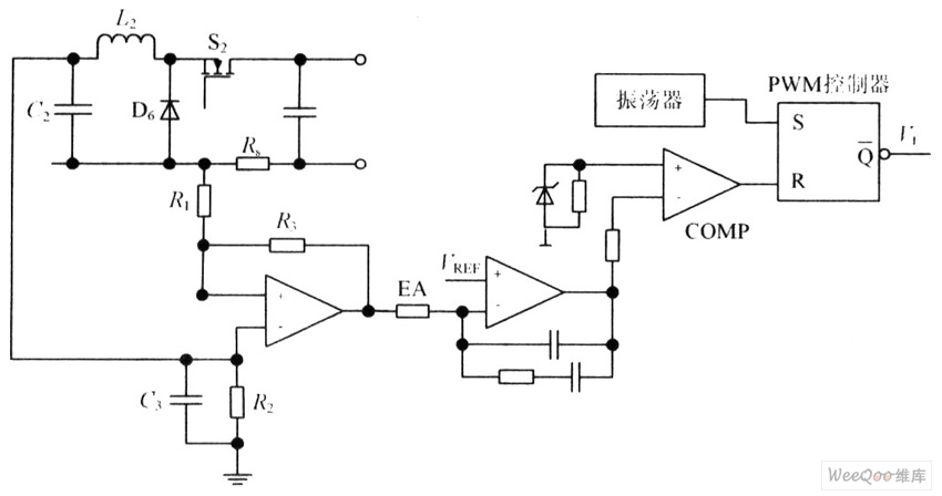
The circuit is capable of enhancing the system power factor to a value exceeding 0.99. It effectively reduces the waveform distortion of the input supply current, ensuring compliance with GB15144 standards, with a distortion index lower than level L....
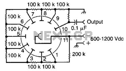
This circuit is representative of the typical application of a photomultiplier tube. The circuit depicted is AC coupled; however, if DC coupling is required, the capacitor can be removed, and an appropriate interfacing method should be employed. A common...