
Automotive Bldc Motor Control For Psoc

The Zetex ZXLD1362 is a highly efficient LED driver IC that operates as a hysteretic converter, making it particularly suitable for automotive interior lighting applications. This IC is designed to deliver a constant output current of up to 350mA, which is ideal for driving high-brightness LEDs. The device's efficiency is a significant advantage, as it reduces heat generation and allows for a more compact design by lowering the need for extensive heat sinking.
The circuit implementation using the ZXLD1362 incorporates a few key components, including input and output capacitors, an inductor, and a sense resistor to regulate the output current accurately. The input capacitor stabilizes the input voltage, while the output capacitor smooths the current delivered to the LEDs, ensuring consistent brightness. The inductor is crucial in maintaining the required current flow, and its value is selected based on the desired output specifications and switching frequency.
The hysteretic control method employed by the ZXLD1362 enhances the response time of the driver, allowing it to adapt quickly to changes in load conditions. This feature is particularly beneficial in automotive environments, where voltage fluctuations can occur due to varying engine loads or battery conditions. Additionally, the ZXLD1362 includes built-in protections such as thermal shutdown and overcurrent protection, ensuring reliable operation under adverse conditions.
Figures 2 and 3 provide a detailed schematic and board layout of the 350mA LED driver circuit, illustrating the arrangement of components and their interconnections. These figures serve as a valuable reference for engineers looking to implement the ZXLD1362 in their designs, showcasing the simplicity and effectiveness of the circuit configuration. Overall, the ZXLD1362 LED Driver IC presents a robust solution for automotive lighting applications, balancing efficiency, simplicity, and reliability.This application note describes a driver solution developed using the Zetex ZXLD1362 LED Driver IC for an automotive EMC compliant solution. ZXLD1362 Switching Regulator allows to maximize the efficiency gains offered by LED lighting solutions in automotive applications, while reducing the component count and the complexity of the circuit.
ZXLD136 2 Description The ZXLD1362 hysteretic converter features CAN be Interior lighting application using ZXLD1362 BR>Figures 2 and 3 show the schematic and the board view of a 350mA LED Driver circuit using 🔗 External reference
Related Circuits
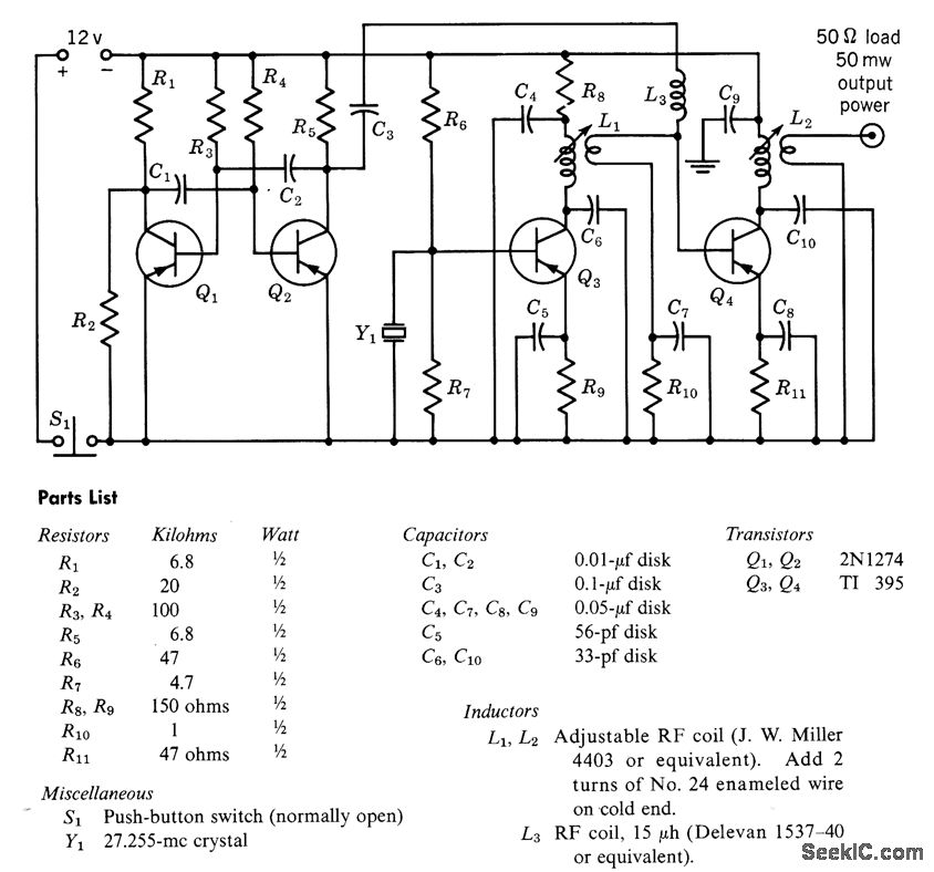
A free-running multivibrator activates power amplifier Q4 for audio applications. The operational range is approximately 1 mile, and capacitor C6 is used to tune the collector of the oscillator to the crystal frequency. - Texas Instruments Inc., "Transistor Circuit...
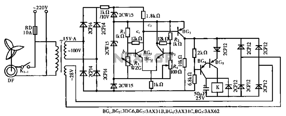
The circuit is a bistable circuit where each bistable unit is controlled by high and low output levels. When power is supplied to the circuit, current flows through components R13, CL, and VD to VD2 for full-wave rectification. The...
When a key is pressed, the remote control transmits a preamble followed by 32 bits of information encoded using specific pulse timings. The pulse examples can be observed in logic analyzer screen captures, although some glitches are present due...
It is a single integrated circuit that includes EEPROM, RAM, an analog-to-digital converter, numerous digital input and output lines, timers, and a UART for RS-232 communication, among other features. A complete programming environment is available for Linux, allowing programming...
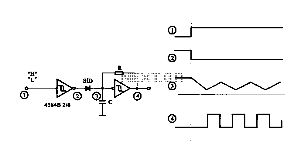
The circuit generates a controlled pulse signal. When a high pulse signal is applied to the input terminal O (start), the output pulse signal is activated. Conversely, when a low signal is received at the input terminal O (stop),...
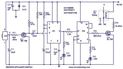
555 Timer TV Remote Controlled Home Appliance Circuit Diagram. Features: 555 timer IC to avoid fast switching. You can only switch the circuit. The 555 timer integrated circuit (IC) is a versatile component widely used in various electronic applications, including...