
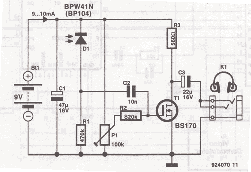
mic recorder circuit

The proposed voice sound recording circuit can be designed using a microcontroller or dedicated audio recording ICs, along with an amplifier for playback. The circuit can be structured as follows:
1. **Microcontroller/Recording IC**: A microcontroller with an integrated ADC (Analog to Digital Converter) or a dedicated audio recording IC, such as the ISD1820, can be used to capture and store audio. The recording duration and quality can be adjusted based on the specifications of the chosen IC.
2. **Microphone**: A small electret microphone can be employed to capture sound. The microphone should be connected to the input of the recording IC. A biasing resistor may be necessary to provide the required voltage to the microphone.
3. **Trigger Mechanism**: A push button or a motion sensor can serve as the trigger mechanism. When activated, it sends a signal to the microcontroller or recording IC to start recording. This can be implemented using a simple GPIO pin configuration.
4. **Playback Circuit**: After recording, the same trigger mechanism can be used to initiate playback. The recorded sound can be played back through a small audio amplifier circuit. A Class D amplifier, such as the PAM8403, can be used for efficient amplification. The output of the recording IC feeds directly into the amplifier's input.
5. **Power Supply**: The entire circuit can be powered by a battery or a DC power supply. Voltage regulators may be necessary to ensure that the components receive the correct operating voltage.
6. **Output**: The output of the amplifier can be connected to a speaker or headphones, depending on the intended application. The speaker should be selected based on the power output of the amplifier and the desired sound quality.
This circuit can be further enhanced by adding features such as LED indicators for recording and playback status, or volume control using a potentiometer.I want to build a voice sound recording circuit that when triggered will play it recorded sound through an amplifier circuit.. 🔗 External reference
Related Circuits
This wireless headphones transmitter ensures quality reception over a distance of 2 meters. The oscillator frequency ranges from 1750 kHz to 3500 kHz, and for the antenna, it... The wireless headphones transmitter operates within a frequency range of 1750 kHz...
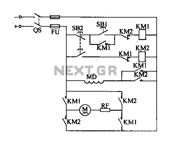
A DC motor reverse brake circuit is presented. To initiate braking, the stop button (SB2) is pressed, which disconnects the move-off contact, causing KM1 to lose power and release. Subsequently, the brake contactor (KM2) is activated. KM2 is designed...
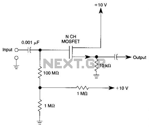
Biasing methods for an N-channel MOSFET to form a unity-gain noninverting amplifier or source-follower. The N-channel MOSFET can be utilized in various configurations, with one common application being the unity-gain noninverting amplifier, also known as a source-follower. In this configuration,...
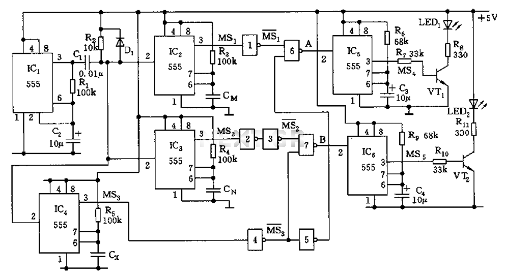
The capacitor filter operates by measuring the capacitance, which is proportional to the pulse width. This measurement is compared to a nominal capacitance to determine qualification. The circuit, as illustrated in the accompanying figure, includes IC1 along with resistors...
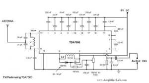
The following circuit illustrates a Single Chip FM Radio Circuit. This circuit is based on the IC TDA 7000 or TDA 7400. Features include a low-cost FM radio circuit. The Single Chip FM Radio Circuit utilizing the TDA 7000 or...
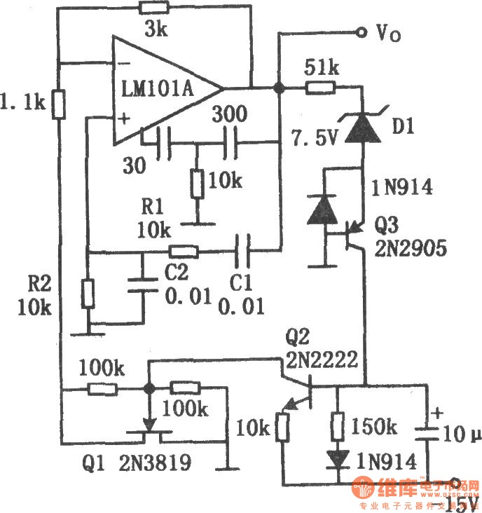
The chart illustrates the Wien bridge sine wave oscillator circuit. The amount of negative feedback in the circuit is determined by the internal resistance of the FET. When the peak output voltage of the oscillator reaches the regulated voltage...