
Averager and Peak Hold/Extender Signal Conditioner

The signal averager circuit utilizes two operational amplifiers (op-amps) to achieve signal averaging through amplification and rectification. The first op-amp functions as a non-inverting amplifier, which boosts the input signal to a desired level while maintaining its phase. The output of this amplifier feeds into the second op-amp configured as an active rectifier. This active rectifier converts the amplified AC signal into a DC level, allowing for averaging over time.
The circuit typically includes feedback resistors that determine the gain of the amplifiers, along with diodes that ensure the rectification process only allows positive voltages to pass, effectively eliminating negative portions of the signal. Capacitors may also be incorporated to smooth out the output, providing a more stable average value.
In practical applications, this signal averager circuit can be used in various fields such as audio processing, sensor signal conditioning, and any scenario where it is necessary to obtain the average value of fluctuating signals. The careful selection of component values is critical to ensure the desired frequency response and accuracy of the averaging process.A signal averager circuit can be formed by an amplifier and active signal rectifier, which is implemented using two operational amplifiers in this circuit. The.. 🔗 External reference
Related Circuits
For many applications, it is necessary to delay signals. Consider applications in automation and control systems. A signal delay circuit can be established using two monoflops. Signal delay circuits play a crucial role in various electronic applications, particularly in automation...
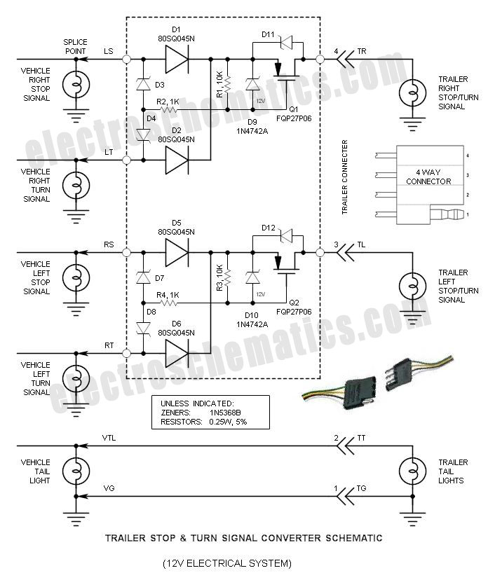
If you have ever wondered why the Stop/Turn signal lamps on your trailer appear dim, you are not alone. The reason for this is that the typical Stop & Turn Signal Converter... The dimming of trailer Stop/Turn signal lamps is...
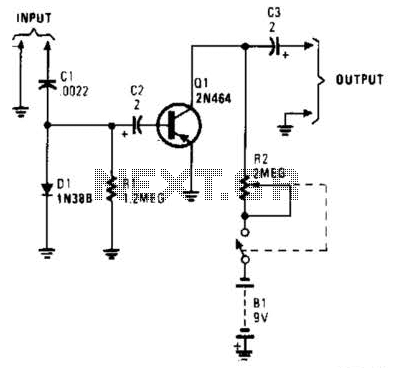
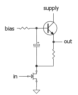
In this circuit, C1, D1, and R1 form an envelope detector. C2 couples audio to the base of Q1. R2 can be adjusted for the desired gain. The circuit under discussion utilizes an envelope detector, which is a fundamental component...
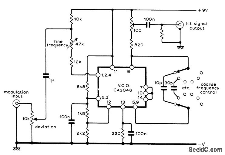
A sine-wave input can be applied to an RCA CA3046 transistor array configured as a voltage-controlled oscillator (VCO), which functions effectively as a low-distortion frequency modulation (FM) signal generator. When a sawtooth input is utilized, the same configuration operates...
The audio source will be a line-level audio signal ranging from -2V to +2V AC, which will be passed through a 220µF coupling capacitor followed by a two-pole low-pass filter (RC). The signal will be processed by an Analog-to-Digital...
Crowbar circuits are named for their function, which resembles dropping a crowbar across electrical terminals. They are employed only as a last resort and should only be used where the connected circuit is adequately fused or includes other protective...