
Trailer Stop & Turn Signal Converter

The dimming of trailer Stop/Turn signal lamps is a common concern among users. This phenomenon often arises due to the inherent design of the Stop & Turn Signal Converter, which is responsible for managing the electrical signals sent to the lamps. The converter typically operates by modulating the voltage and current supplied to the lamps, which can lead to reduced brightness when standard incandescent bulbs are used.
In many cases, the issue can be exacerbated by poor connections, inadequate wiring, or the use of lower-quality components. For example, if the wiring gauge is too small for the current being drawn, it can result in voltage drops that diminish the brightness of the lamps. Furthermore, if the converter is not compatible with the specific type of lamps installed, this can also lead to insufficient power being delivered.
To address these issues, it is advisable to inspect the entire circuit, including the connections at the converter, the integrity of the wiring harness, and the specifications of the lamps being utilized. Upgrading to LED lamps can also provide a solution, as they require less power and generally produce brighter light output compared to traditional incandescent bulbs. Additionally, ensuring that the converter is rated appropriately for the load it will control can further enhance performance and brightness.
In summary, understanding the factors that contribute to dim Stop/Turn signal lamps is essential for effective troubleshooting and ensuring optimal visibility and safety while towing.If you ever wondered why your trailer Stop/Turn signal lamps are so dim you are not alone. The answer is simply that the typical Stop & Turn Signal Convert.. 🔗 External reference
Related Circuits
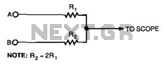
This simple resistor circuit can be used to trick an oscilloscope into displaying two logic signals on one channel. By selecting R2 to be twice the value of R, the oscilloscope trace will show one of four distinct analog...
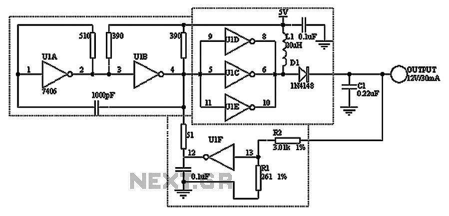
A TTL hex inverter circuit can function as a DC/DC converter, converting 5V to 12V. This circuit encompasses all necessary functionalities for DC/DC conversion. It relies on a TTL switching threshold voltage regulator. The components U1A and U1B form...
A signal averager circuit can be formed by an amplifier and active signal rectifier, which is implemented using two operational amplifiers in this circuit. The signal averager circuit utilizes two operational amplifiers (op-amps) to achieve signal averaging through amplification and...
As depicted in the image, when the output current surpasses 40mA, the internal resistance of 50Ω in the XTR110 (R9) must be substituted with an external resistance, REXT. This external resistance is connected between pins 13 and 16. The...
By using the same circuit of the Digital Stopwatch 0-99sec, we can add an AND gate and transform the 0 to 99sec stopwatch to a 0 to 60sec stopwatch. We must find a way to control the RESET function...
The circuit depicted in the figure allows for the selection of optimal operating conditions and a suitable allocation of the temperature coefficient for the resonant circuit components. The resonance occurs at both ends of the circuit. Additionally, the exchange...